Table of Contents
Advertisement
Quick Links
Advertisement
Table of Contents

Subscribe to Our Youtube Channel
Related Manuals for Nidec LEROY-SOMER FFB


Summary of Contents for Nidec LEROY-SOMER FFB
- Page 1 Installation guide Brake motors Before any intervention or operation for preventive or corrective maintenance, please, download NECESSARILY the update version of Maintenance guide reference 5287: www.leroy-somer.com Reference: 5286 en - 2017.09 / c...
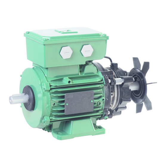
- Page 2 GENERAL WARNING This document complements general manual ref. 1889 (recommendations), ref. 4850 (LSES motor), ref. 4155 (LSRPM motor) and guide FFB brake maintenance ref. 5287. All documents are downloadable : www.leroy-somer.com FFB brake motors are units consisting of an induction motor and a failsafe braking system (safety brake). This brake motor benefits from the experience of one of the largest manufacturers in the world, using state-of-the-art technology in automation, specially selected materials and rigorous quality control.
-
Page 3: Table Of Contents
CONTENTS 1 - RECEIPT ................................4 1.1 - Identification ............................... 4 1.2 - Storage ................................ 4 2 - RECOMMENDATIONS ............................4 2.1 - Commissioning ............................4 2.2 - Mechanical installation ..........................4 2.2.1 - Brake with options ..............................5 2.3 - Electrical connection ............................ 5 2.3.1 - Terminal box ................................. -
Page 4: Receipt
RECEIPT 1 - RECEIPT Marking : Legal mark of conformity of product to the requirements Check the state of the brake motor; if there is any damage to of European Directives the motor or even its packaging, inform the carrier. ®... -
Page 5: Brake With Options
RECOMMENDATIONS 2.3 - Electrical connection Do not knock the motor (terminal box, cover), the shaft or the coupling during mounting, do not crush the seal, do not The cables should be connected with the power project beyond the shoulder of the shaft. off by qualified personnel, in accordance with Ensure correct brake motor cooling, the air intakes and outlets good practice, in compliance with the safety... -
Page 6: Terminal Box
WIRING DIAGRAMS 2.3.1 - Terminal box (TB) of FFB brake motors The terminal box is watertight once the cable glands have been fitted and each cable gland is tightened on the cable according The standard terminal box of the FFB brake motor has holes to its cable size. -
Page 7: Brake Coil
WIRING DIAGRAMS ➀ ➁ ➁ Brake motor: wiring diagram under the TB cover 180 VDC brake coil: 2-speed motor, 2 windings, 1 voltage, built-in power supply IMPORTANT W2 T6 U2 T4 V2 T5 Débrancher le bloc redresseur **S08 pour essai d’isolement ou diélectrique Disconnect the rectifier cell when testing for current insulation or dielectric V1 T2... -
Page 8: Forced Ventilation Unit
WIRING DIAGRAMS 3.4 - Forced ventilation - Thermal protection Standard thermal protection Class F, 150°C LS 71 (F)LS(ES) 80 to 132 Double PTO Triple PTC (single phase) (single phase) 230 or 400 V SINGLE-PHASE FORCED VENTILATION 1-ph 230 V for frame size 80 --> 132 for frame size 71 Breaking current 1.6 A - cos φ... -
Page 9: Regular Servicing
REGULAR SERVICING 4 - REGULAR SERVICING - COMMANDER ID300/302 (see manual Commander ID300/302 P.N. 5511) Checks after start-up After approximately 50 hours’ operation, check that the screws fixing the motor and the coupling device are still tight. In the case of chain or belt transmission, check that the tension is Optional correctly adjusted. -
Page 10: Preventive Maintenance
PREVENTIVE MAINTENANCE 5 - PREVENTIVE MAINTENANCE 6 - USE IN EXAT ZONE 22 Special marking (EXAT) ➉ (§1.1): Before any intervention or operation for preventive or corrective maintenance, please, FFB 3 download NECESSARILY the update version of Mf : 6.5 kg 52 Nm Maintenance guide reference 5287: S N°... - Page 11 PREVENTIVE MAINTENANCE PS4 : INSPECTION, MEASURING & TEST EQUIPMENT MANAGEMENT Classement/File: S4T032 DÉCLARATION UE DE CONFORMITÉ ET Révision: B Page : 2 / 2 Date: 21/06/2017 D'INCORPORATION Moteur (F)LS(ES) associé à un Frein FCR ou FFB Annule et remplace/Cancels and RABION en zone 22 replaces : A du 01/12/2016...
- Page 12 Moteurs Leroy-Somer Headquarter: Boulevard Marcellin Leroy - CS 10015 16915 ANGOULÊME Cedex 9 Limited company with capital of 65,800,512 € RCS Angoulême 338 567 258 www.leroy-somer.com...
Need help?
Do you have a question about the LEROY-SOMER FFB and is the answer not in the manual?
Questions and answers