
Related Manuals for Nidec LEROY-SOMER FFB Series


Summary of Contents for Nidec LEROY-SOMER FFB Series
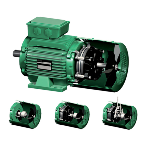
- Page 1 Maintenance Guide Maintenance Guide Brake motors Reference: 5287 en - 2019.07 / d...
- Page 2 GENERAL WARNING This document is an addition to the general manual ref. 1889 (recommendations), ref. 4850 (LSES motor), ref. 4155 (LSRPM motor), and the installation manual ref. 5286. FFB brake motors are assemblies made of an asynchronous motor and a failsafe braking system (safety brake). This brake motor benefits from the experience of a global manufacturer, using cutting edge technologies - automation, selected materials, thorough quality control - in our motor plants who have been awarded the ISO 9001 - Issue 2008 international certification.
-
Page 3: Table Of Contents
CONTENTS 1 - IDENTIFICATION ..............................4 1.1 - Standard plate ............................. 4 1.2 - Special marking ............................4 2 - SPARE PARTS ..............................5 2.1 - Procedure ..............................5 2.2 - Spare parts ..............................5 3 - EXPLODED VIEW AND PARTS LIST OF FFB BRAKE MOTORS ..............6 3.1 - Exploded view and parts list for (F)LS(ES) FFB brake motor ............... -
Page 4: Identification
IDENTIFICATION 1 - IDENTIFICATION Marking : Legal mark of conformity of product to the requirements 1.1 - Standard plate of European Directives Motor nameplate (item 26a) ® : CSA certified product, UL conformity 166631 Motor plate LSES112MU 4kW, 4p, 400V LS 90 L N°... -
Page 5: Spare Parts
SPARE PARTS 2 - SPARE PARTS 2.1 - Procedure Always indicate the following when ordering spare parts: - complete motor type, its number and the information indicated on the information plate (refer to §1); - serial no. of the brake information plate item 26b; - the numbers and descriptions of the parts (record the part marks in the exploded view §2.1 and their description in the parts list §2.2). -
Page 6: Exploded View And Parts List Of Ffb Brake Motors
EXPLODED VIEW AND PARTS LIST OF FFB BRAKE MOTORS 3 - EXPLODED VIEW AND PARTS LIST OF FFB BRAKE MOTORS 3.1 - Exploded view and parts list for (F)LS(ES) FFB brake motor 1110 0071 1303 Item Description 1302 Stator 0054 0006 Housing 0050... -
Page 7: Exploded View, Parts List Aluminium Ffb Brake Motor: Size 160 And 180 Or Cast Iron: Size 160
EXPLODED VIEW AND PARTS LIST OF FFB BRAKE MOTORS 3.3 - Exploded view, parts list Aluminium FFB brake motor: size 160 and 180 or Cast iron: size 160 0071 0093 0092 0069 0021 0033 0030 0005 0039 0054 0273 0275 0274 0629 0006... -
Page 8: Corrective Maintenance
CORRECTIVE MAINTENANCE 4 - CORRECTIVE MAINTENANCE - Remove the brake disc 1101 while recording the assembly direction (large hub shoulder on motor side). Before any operation on the brake, always - Unscrew the fixing screws 1305 from the face plate, then disconnect the brake motor from its power remove the face plate 1100. -
Page 9: Air Gap Adjustment
CORRECTIVE MAINTENANCE 4.4 - Air gap adjustment - Screw the spacers 1104 in abutment on friction face-plate (tighten to 2 Nm ±10% torque). The air gap requires adjusting when it reaches 0.9 mm.. - Tighten fixing screws 1106 brake yoke on face-plate to the Lining wear must be checked when the air gap is adjusted, by torque as follows: checking the disc thickness (R). -
Page 10: Characteristics
CHARACTERISTICS 5 - CHARACTERISTICS 5.1 - Braking moments The braking torque is defined according to the number, position of the springs and their colour, according to the values indicated in the following table. Running-in: all brake linings (complete brake, disc only: see § 2.2) are run-in in the plant before assembly onto the motor. The stated dynamic braking torque is optimum (tolerance from -10 to +40%). -
Page 11: Options
OPTIONS 6 - OPTIONS 6.1 - DLRA lever 1105 1401 - Exploded view 1500 1502 1501 1505 0008 0007 0009 0013 0027 1406 1407 1503 1504 - Parts list Item Description Item Description 1407 Fixing screw Fan thrust washer 0 or 1 1500 Stud Locking circlips 1501 DLRA calliper... -
Page 12: Dlm Lever
OPTIONS 6.2 - DLM lever - Exploded view 1502 1401 1505 1605 1602 0008 0007 0009 0013 0027 1406 1407 1500 1501 1503 1504 1600 1603 1601 1604 1800 - Parts list Item Description Item Description 1503 Spiral spring under nut Fan thrust washer 0 or 1 1504... -
Page 13: Dmd Lever
OPTIONS 6.3 - DMD lever - Exploded view 1401 1500 1502 1505 1600 1603 1605 1702 1602 1703 1704 1700 0008 0007 0013 0027 1406 1407 1501 1503 1504 1601 1701 0009 - Parts list Item Description Item Description 1505 Return spring (item 1501) Fan thrust washer (item 7) 0 or 1... -
Page 14: Marks (Loosening-Wear)
OPTIONS 6.4 - Marks (Loosening-Wear) 6.4.2 - Loosening indicator 6.4.1 - Wear mark - Exploded view 1906 - Exploded view 1100 1901 1900 1105 1903 1902 1905 1904 1102 1102 1907 - Parts list - Parts list Item Description Item Description 1105 Yoke... -
Page 15: Speed And Position Feedback Devices
OPTIONS 6.6 - Speed and position feedback devices - Exploded view FFB brake + incremental or absolute encoder (Aluminium: size 71 to 180 or cast iron: size 80 to 160) 1802 1803 159/2 1400 1800 1401 159/1 1403 1404 - Parts list Item Description Item... -
Page 16: Forced Ventilation Kit
OPTIONS 6.7 - Forced ventilation kit 6.9 - Particular conditions of use - Exploded view - Thermal protections (§8) 1405 - Heating resistors (§8) - Surface temperatures: As standard, the maximum temperature of our brake motors is +125°C with a maximum ambient temperature ≤ +40°C. Without derating the brake motor, the maximum surface temperature shall be: •... -
Page 17: Use In Atex Zone 22
OPTIONS 6.10 - Use in Atex zone 22 Specific ATEX 11 marking (§1.1): FFB 3 Mf : 6.5 kg 52 Nm S N° : 9999999/001 FFB370NU001 U : 180 VDC I : 345 mA Nmax : 3600 rpm II 3 D Ex tc IIIB T125°C Dc Motor size : 168 II 3D Ex tc IIIB: Group II, category 3, non- conductive dusts. -
Page 18: Repair Guide
REPAIR GUIDE 7 - REPAIR GUIDE Incident Possible cause Remedy Abnormal noise From motor or driven machine? Disconnect the motor from the driven device and test the motor alone Noisy brake motor Mechanical cause: if the noise persists after powering Check that the key complies with the type of balancing - Check the condition of the bearings - Vibrations... -
Page 19: Connection Diagrams
CONNECTION DIAGRAMS 8 - CONNECTION DIAGRAMS 8.2.2 - 180VDC brake coil for 2-speed motor with 8.1 - Motor: reminder 2 windings, 1 voltage, built-in supply Œ Check the rotation direction of the drive shaft. IMPORTANT Débrancher le bloc redresseur L1 - L2 - L3 L1 - L3 - L2 pour essai d’isolement ou diélectrique... -
Page 20: Options
CONNECTION DIAGRAMS 8.3 - Options 8.3.5 - Speed and position encoders Ž 8.3.1 - Standard thermal protections, class F, Standard incremental encoder: 5VDC 1024 pts/tr or 4096 150°C pts/tr Separate supply brake Double PTO Triple CTP Thermal Terminal No. Connection Colour protections... -
Page 21: Recycling
RECYCLING 8.3.9 - VARMECA 33 / 34 option Three phase forced ventilation for (F)LS(ES) 160, 180 THREE PHASE FORCED VENTILATION ESFR VMA 33/34 HA 160 Dedicated logic output 1 SPEED - 2 VOLTAGES L1 - L2 - L3 Opto Triac 1.25 A VMA 33/34T 600 V... - Page 22 NOTES CONNECTION DIAGRAMS FFB Brake Motors Maintenance Guide 5287 en - 2019.07 / d...
- Page 23 NOTES CONNECTION DIAGRAMS FFB Brake Motors Maintenance Guide 5287 en - 2019.07 / d...
- Page 24 Moteurs Leroy-Somer SAS Siège social : Boulevard Marcellin Leroy - CS 10015 16915 ANGOULÊME Cedex 9 Société par Actions Simplifiées au capital de 65 800 512 $ RCS Angoulême 338 567 258 www.leroy-somer.com...
Need help?
Do you have a question about the LEROY-SOMER FFB Series and is the answer not in the manual?
Questions and answers