Table of Contents
Advertisement
Quick Links
Advertisement
Table of Contents

Related Manuals for THORLABS MX10A


Summary of Contents for THORLABS MX10A
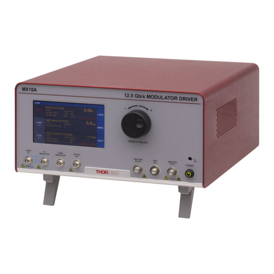
- Page 1 MX10A or MX40A 12.5 Gb/s Modulator Driver 40 Gb/s Modulator Driver User Guide...
-
Page 2: Table Of Contents
MX10A, MX40A Modulator Driver Table of Contents Chapter 1 Warning Symbol Definitions .................... 1 Chapter 2 Safety ............................ 2 Chapter 3 Introduction .......................... 4 3.1. Description ........................4 3.2. Intensity or Phase Modulators ..................4 3.3. Parts List .......................... 4 3.4. Block Diagram ......................... 5 ... - Page 3 MX10A, MX40A Modulator Driver Chapter 11 Regulatory ...........................31 Chapter 12 Declaration of Conformity ....................32 Chapter 13 Thorlabs Worldwide Contacts ..................34 TTN035544-D02...
-
Page 4: Chapter 1 Warning Symbol Definitions
MX10A, MX40A Modulator Driver Chapter 1: Warning Symbol Definitions Chapter 1 Warning Symbol Definitions Below is a list of warning symbols you may encounter in this manual or on your device. Symbol Description Direct Current Alternating Current Both Direct and Alternating Current... -
Page 5: Chapter 2 Safety
MX10A, MX40A Modulator Driver Chapter 2 Safety All statements regarding safety of operation and technical data in this instruction manual will only apply when the unit is operated correctly. If equipment is used in a manner not specified by the manufacturer, the protection provided by the equipment may be impaired. - Page 6 This product is not suitable for household room illumination. Inputs and outputs must only be connected with shielded connection cables. Only with written consent from Thorlabs may changes to single components be carried out or components not supplied by Thorlabs be used.
-
Page 7: Chapter 3 Introduction
Item # into the search field. Thorlabs’ technical support can provide up-to-date information on available firmware revisions and control functions. NOTE: This manual covers both the MX10A and MX40A models, as their architectures are very similar. Differences are clearly noted in the following sections. 3.2. -
Page 8: Block Diagram
MX10A, MX40A Modulator Driver Chapter 3: Introduction 3.4. Block Diagram These instruments provide all the electronics and control circuitry to bias and drive high-speed, fiber-coupled, intensity or phase modulators. The user supplies the laser source, the signal source, and the modulator of their choice. -
Page 9: Front And Rear Panel Overview
MX10A, MX40A Modulator Driver 3.5. Front and Rear Panel Overview Feature Description MX10A MX40A Front Panel Touchscreen Display Adjustment Knob Grounding Jack Banana Banana Laser Input PM FC/PC PM FC/PC Laser Output to Modulator PM FC/PC PM FC/PC Return from Modulator... -
Page 10: Chapter 4 Quick Start Guide
MX10A, MX40A Modulator Driver Chapter 4: Quick Start Guide Chapter 4 Quick Start Guide ESD CAUTION Caution – The components inside this instrument are ESD sensitive. Take all appropriate precautions to discharge personnel and equipment before making any connections to the unit. A front panel grounding jack is provided for connection to a wrist strap. -
Page 11: Controls On The Home Page
Controls on the Home Page The MX10A and MX40A can be fully controlled by using the resistive touchscreen display for all functions. You can use a finger or a plastic stylus to make selections on the screen. In addition, the knob on the front panel can be used in place of the on-screen arrow buttons for quickly changing set-point values. -
Page 12: Controls In The Settings
MX10A, MX40A Modulator Driver Chapter 4: Quick Start Guide 4.3. Controls in the Settings Pages The Settings pages all follow the same general design and functionality as shown in the example screen shot below. The upper section with white letters displays the parameters that can be changed. Simply tap on the parameter of interest to highlight it, and the controls for that parameter will be presented. -
Page 13: Chapter 5 Operating Instructions
MX10A, MX40A Modulator Driver Chapter 5 Operating Instructions 5.1. The Modulator Transmission Function (Intensity Modulators Only) The intensity modulator (e.g. MZM) has a repetitive transmission function with applied voltage as can be seen in the diagram below. In order for it to work correctly, a DC bias voltage must be applied and maintained at the desired set point. -
Page 14: Bias Settings Page (Intensity Modulators Only)
MX10A, MX40A Modulator Driver Chapter 5: Operating Instructions 5.3. Bias Settings Page (Intensity Modulators Only) To get to the Bias Settings page tap the Bias monitors pane on the Home page. The Bias page contains the settings for controlling the modulator bias and operating modes. There are four modes for modulator bias control: 1) Quadrature, 2) Peak, 3) Null, and 4) Manual. - Page 15 MX10A, MX40A Modulator Driver 5.3.1. Quadrature Mode Quadrature is the default mode and biases the modulator at the 50% point on the modulator transmission curve (see figure). This is the recommended mode for digital signals such as On-Off-Keying (OOK) that require a high extinction ratio.
- Page 16 MX10A, MX40A Modulator Driver Chapter 5: Operating Instructions The dither tone frequency may be changed by tapping the Dither Frequency field. Standard frequencies are available on the blue buttons, or a custom frequency may be chosen by pressing User Define. The dither tone frequency usually has very little effect on the accuracy of the bias control, but in some cases a different frequency may work better or be desirable depending on the RF signal applied, or the specific application.
- Page 17 MX10A, MX40A Modulator Driver 5.3.2. Peak Mode The Peak Mode adjusts the DC bias voltage so the transmission is centered at a nearby transmission maximum. In this mode only dither frequency and amplitude settings are available. These controls & settings are the same as previously described for the Quadrature mode.
- Page 18 MX10A, MX40A Modulator Driver Chapter 5: Operating Instructions 5.3.4. Manual Mode The Manual mode allows the user to bias the modulator at any point of the transmission function desired. Manual mode offers two modes of operation: 1) Constant Bias, and 2) Constant Ratio. In both of these modes, the dither function is not active, and the controller uses different techniques to hold the bias steady.
- Page 19 MX10A, MX40A Modulator Driver In the Constant Ratio mode there is an option to select between the two available operating regions by selecting the Slope field. Positive slope is the non-inverting operating point where increasing voltage on the modulator results in increasing optical output power. Negative slope is the inverting operating point where increasing voltage on the modulator results in decreasing optical output power.
-
Page 20: Amplifier Settings Page
MX10A, MX40A Modulator Driver Chapter 5: Operating Instructions 5.4. Amplifier Settings Page To get to the Amplifier Settings page, tap on the Amplifier monitor pane on the Home page. The amplifier has a fixed gain that it applies to a user input signal. The signal is then routed to the RF input port of the modulator via the front panel loop-back cable. - Page 21 MX10A, MX40A Modulator Driver The Crossing Point field allows the user to adjust the eye crossing point in the eye diagram as depicted in the diagram below. It provides an adjustment to optimize the bit-error-rate (BER) performance of a transmission link by adjusting the amplifier’s internal threshold levels.
-
Page 22: Variable Optical Attenuator Settings Page
MX10A, MX40A Modulator Driver Chapter 5: Operating Instructions 5.5. Variable Optical Attenuator Settings Page To get to the Variable Optical Attenuator (VOA) Settings page tap in the VOA monitors pane on the Home page. The VOA provides the means for adjusting and stabilizing the output power after the modulator. -
Page 23: Load Page
MX10A, MX40A Modulator Driver 5.6. Load Page To get to this page, tap the blue Load button on the Home page. The Load page has several instrument settings stored as presets for operating the instrument in different standard modes. Applying a preset is a fast way to put the instrument in a known state. -
Page 24: Menu Page
MX10A, MX40A Modulator Driver Chapter 5: Operating Instructions 5.7. Menu Page To get to this page tap the blue Menu button on the Home page. The Menu page has links to several pages that allow the user to control the display, sounds, lights, and get help information. The following sections describe these functions in more detail. - Page 25 MX10A, MX40A Modulator Driver 5.7.2. System Information Page Path here: Home > Menu > System Information. The System Information page displays the installed hardware and software versions This is useful information when in the need for tech-support or to verify firmware revisions 5.7.3.
- Page 26 5.7.4. Thorlabs Help Page Path here: Home > Menu > Thorlabs Help The Thorlabs Help page displays the Tech Support phone number, Thorlabs web site, and the installed hardware and software versions. This information will be useful when speaking with Tech Support.
-
Page 27: Chapter 6 Specifications
MX10A, MX40A Modulator Driver Chapter 6 Specifications All Specifications are at 1550 nm and 25 °C ambient temperature, unless otherwise noted. Specifications that are specific to the MX10A or MX40A will be marked as (MX10) or (MX40). 6.1. General System Specifications Parameter... -
Page 28: Internal Amplifier Specifications
MX10A, MX40A Modulator Driver Chapter 6: Specifications 6.4. Internal Amplifier Specifications Parameter Typical Values Notes 35 ps (MX10A) Large signal, digital response Rise/Fall Time 8 ps (MX40A) 34 dB (MX10A) RF Amplifier Gain 30 dB (MX40A) 7 GHz (MX10A) Linear, analog response... -
Page 29: General Purpose I/O, Rs-232, And Usb Connections
The back panel has connectors for monitor and control functions, as well as for upgrading the firmware. Both the RS-232 and the USB connections can be used for remotely controlling the MX10A and MX40A via SCPI type serial commands. Which connector to choose for remote control operation depends on the demands of the application and the user’s preference. -
Page 30: Chapter 8 Mechanical Drawings
MX10A, MX40A Modulator Driver Chapter 8: Mechanical Drawings Chapter 8 Mechanical Drawings 122.0 mm 134.8 mm (4.80") (5.31") 250.0 mm (9.84") 300.0 mm (11.81") 322.2 mm (12.69") Page 27 Rev B, October 5, 2017... -
Page 31: Chapter 9 Maintenance, Repair & Fuses
Fiber end-face cleaner for patch cords The optical connectors on the front panel may be cleaned using a 2.5 mm bulkhead cleaner such as the Thorlabs FBC1. This allows the user to clean the fiber end-face without removing it from the internal bulkhead adapter. -
Page 32: Replacing The Main Fuse
5. Investigate the fuse. This can be done with a simple continuity check. If in doubt, replace the fuse. A spare fuse is stored in the fuse holder. Additional replacement fuses can be purchased from Thorlabs. Always use fuses of the same type as the original. -
Page 33: Chapter 10 Troubleshooting
In case you experience any problems, below are a few checks to help in troubleshooting the problem. If you have any questions, please contact your local Thorlabs Technical Support office. If the unit does not appear to turn on correctly, please check the following items: ... - Page 34 Waste Treatment is Your Own Responsibility If you do not return an “end of life” unit to Thorlabs, you must hand it to a company specialized in waste recovery. Do not dispose of the unit in a litter bin or at a public waste disposal site.
- Page 35 MX10A, MX40A Modulator Driver Chapter 12 Declaration of Conformity Page 32 TTN035544-D02...
- Page 36 MX10A, MX40A Modulator Driver Chapter 12: Declaration of Conformity Page 33 Rev B, October 5, 2017...
- Page 37 MX10A, MX40A Modulator Drive Chapter 13 Thorlabs Worldwide Contacts For technical support or sales inquiries, please visit us at www.thorlabs.com/contact for our most up-to- date contact information. USA, Canada, and South America UK and Ireland Thorlabs, Inc. Thorlabs Ltd. sales@thorlabs.com sales.uk@thorlabs.com...
- Page 38 www.thorlabs.com...
Need help?
Do you have a question about the MX10A and is the answer not in the manual?
Questions and answers