Table of Contents
Advertisement
Quick Links
Advertisement
Table of Contents

Related Manuals for Acuity AccuRange AR1000


Summary of Contents for Acuity AccuRange AR1000
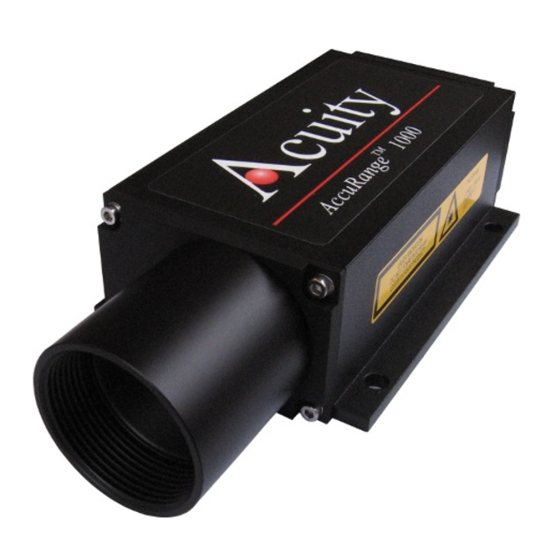
- Page 1 AccuRange AR1000™ Laser Distance Sensor AccuRange AR1000H™ Laser Distance Sensor w/ Heater User’s Manual Rev. 1.7 For use with AR1000™ and AR1000H™ 1/12/2010 Acuity A product line of Schmitt Industries, Inc. 2765 NW Nicolai St. Portland, OR 97210 www.acuitylaser.com...
- Page 2 Limited Use License Agreement CAREFULLY READ THE FOLLOWING TERMS AND CONDITIONS BEFORE OPENING THE PACKAGE CONTAINING THE PRODUCT AND THE COMPUTER SOFTWARE LICENSED HEREUNDER. CONNECTING POWER TO THE MICROPROCESSOR CONTROL UNIT INDICATES YOUR ACCEPTANCE OF THESE TERMS AND CONDITIONS. IF YOU DO NOT AGREE WITH THE TERMS AND CONDITIONS, PROMPTLY RETURN THE UNIT WITH POWER SEAL INTACT TO THE DEALER FROM WHOM YOU PURCHASED THE PRODUCT WITHIN FIFTEEN DAYS FROM DATE OF PURCHASE AND YOUR PURCHASE PRICE WILL...
- Page 3 Procedures for Obtaining Warranty Service 1. Contact your Acuity distributor or call Schmitt Industries, Inc. to obtain a return merchandise authorization (RMA) number within the applicable warranty period. Schmitt Industries will not accept any returned product without an RMA number.
-
Page 4: Table Of Contents
User’s Manual for the AR1000™ Series Laser Distance Sensor Rev. 1.7 For use with AR1000 and AR1000H Table of Contents INTRODUCTION ...............................1 1.1...........................1 ENERAL VERVIEW 1.2..........................2 EFINITION OF ERMS 1.3........................2 UICK TART NSTRUCTIONS 1.3.1. Mounting..............................2 1.3.2. Serial Data Wires ..........................3 1.3.2.1. - Page 5 SERIAL INTERFACE OPERATION......................15 5.1.........................15 ERIAL ARDWARE NTERFACE 5.1.1. Communications Protocol ........................15 5.1.2. Baud Rate (BR) ............................16 5.2. (SD, SF)........................16 ERIAL UTPUT 5.2.1. ASCII Output Format (SDd , SDh or SDs) ..................16 5.2.2. Serial Data Units or Scale Factor (SFx.x)...................17 5.3.
- Page 6 AR1000 User’s Manual Rev 1/10...
-
Page 7: Introduction
Measurement output can be in the form of serial data (RS232 or optional RS422), Analog Output (4-20mA current loop). Special order sensors include Profibus®, or SSI interfaces. Those interface configurations are not discussed in this manual. Contact Acuity for details. AR1000 User’s Manual... -
Page 8: Definition Of Terms
Do not point the sensor at any person, particularly a person’s eyes or face. Do not attempt to disassemble the sensor or loosen any screws. Improper disassembly will destroy the optical alignment of the sensor and necessitate factory repairs. Do not operate the sensor in areas where the sensor case is exposed to direct sunlight for extended periods or where the air temperature is more than 50°C (122°F) or less than -10°C (14°F). -
Page 9: Serial Data Wires
Connect the orange (Supply +) and blue (Ground) wires of the sensor cable to a 10 to 30 volt DC power supply (or use the power supply if the sensor came with one). 1.3.2. Serial Data Wires The serial connection is required to set up a unit for operation. 1.3.2.1. -
Page 10: General Description
General Description The AR1000H is a laser diode based distance measurement sensor for ranges up to 118 feet (30m) on regular surfaces and up to 500 feet (150 m) using a reflective target. The accuracy is generally specified with a linearity of +/- 0.08 inches (2mm). Linearity will vary depending on temperature and surface reflectivity of the target surface. -
Page 11: Installation
2.3. Installation The AR1000 sensor is typically installed by affixing the sensor to a machined bracket with bolts through the four mounting holes in the sensor. Their location is shown in the mechanical drawing above. The laser should be aimed at a target such that the distance from the reference point to the target can be meausured. -
Page 12: Sensor Maintenance
2.5. Sensor Maintenance The AR1000 sensor requires little maintenance from the user. The sensor lens should be kept clean of dust buildup as a part of regular preventative maintenance. Use compressed air to blow dirt off the window or use delicate tissue wipes. Do not use any organic cleaning solvents on the sensor. -
Page 13: Installation And Checkout
Installation and Checkout 3.1. Mounting Mount the sensor in such a way that the case is not twisted or warped. Using three hard points along the front and back edges or a slightly compliant mounting system are the best methods. Do not clamp or squeeze the sensor case excessively. -
Page 14: Standalone Cabling
3.2.1. Standalone Cabling To use the AR1000 without a serial connection to a host computer, the only connections necessary are the power and ground wires, the analog output wires, and optionally the alarm output wire connecting to your data display, recording, or control equipment. See Signal and Power Interface (section 4) for wire connections. -
Page 15: Power On
3.3. Power On Connect a 15 volt power supply to the power and ground lines of the sensor cable. See Signal and Power Interface (section 4) for wire connections. Only the power and ground need be connected for operation in addition to the serial interface. Caution: be sure that the laser will not cause an eye hazard. -
Page 16: Sensor Output Check
AR1000 accepts the command and sets the baud rate to 9600. The possible baud rates are 2400, 4800, 9600, 19200, and 38400. 3.5.2. Sensor Output Check If the sensor output value is in error, check that the sensor and target are stationary and stable, that the target is at least 4 inches (0.1 m) from the sensor’s lens, and that the laser beam is hitting the target. -
Page 17: Signal And Power Interface
Signal and Power Interface The AR1000 has a multipurpose cable (sensor cable) with solder tail wires. Connection and termination according to the instructions is essential for correct sensor operation. Read the wire descriptions for connection information. Figure 7 AR1000 multipurpose cable with 10 conductors plus shield and corresponding pin arrangments 4.1. -
Page 18: Shield (Clear)
Power supplies from 10 VDC to 30 VDC may be used. Higher voltages will result in excessive current drawn by the over-voltage protection circuitry and may cause permanent damage. Voltages less than 10 VDC may result in inaccurate measurement readings. With the use of the on-board heater, the AR1000 sensor uses 24 W of power at 24 VDC. -
Page 19: Alarm Output (White)
Figure 8 Wiring Diagram for Analog output The best conversion to voltage is obtained by connecting a 500-ohm load resistor (1/4 Watt minimum) between the red and blue wires at the measurement point. This gives a 2 volt to 10 volt output range. -
Page 20: Laser Trigger (Brown)
Figure 10 Wiring diagram for Alarm Output 4.1.6. Laser Trigger (Brown) The Brown wire is the Trigger input. It is normally left unconnected to enable the laser. The trigger input is used with the DF measurement mode or TM trigger mode setting in the AR1000. -
Page 21: Serial Interface Operation
Serial Interface Operation 5.1. Serial Hardware Interface The serial port hardware is installed either as RS232 (order sensor p/n AP1000232) or RS422 (order sensor p/n AP1000422). The installed serial port hardware can only be selected at the time of purchasing the AR1000 sensor. The serial port allows full-duplex operation. 5.1.1. -
Page 22: Baud Rate (Br)
Command Description Sets current distance as offset Turns laser on Turns laser off Displays all parameter values Resets all parameters to standard values 5.1.2. Baud Rate (BR) The Baud Rate is selectable via the serial interface and it requires the host device to change its own Baud Rate after commanding the sensor to change. -
Page 23: Serial Data Units Or Scale Factor (Sfx.x)
The minimum value of 000001 can be reached before the sensor reports an E15 error (see Error Codes Section 5.3). A maximum signal strength value of 99999 may be reached before the sensor becomes overloaded with ambient light and reports an E17 error. Hexadecimal Notes: Hexadecimal output values are calculated on units of millimeters (mm) multiplied by the scale factor SF. -
Page 24: Laser On And Laser Off (Lo, Lf)
Code Description Remediation Reduce ambient light at target and minimize Too much ambient light (sun) shiny surfaces DX mode: measured distance greater Check measurement path for obstacles than specified target range DX mode: target speed > 10 m/s Reduce relative motion speed of target Temperature below 14°F (-10 °C) Increase ambient temperature to 14°F (-10°C) Temperature below 140°F (60 °C) -
Page 25: Resetting Sensor Settings (Pr)
ALARM center[AC]....20 ALARM hysterese[AH]....0.1 ALARM width[AW]....10 heating on[HO]....3 heating off[HF]....12 distance of Iout=4mA [RB]..15 distance of Iout=20mA [RE]..25 remove measurement [RM]...0 0 0 trigger delay, trigger level[TD]..0 0 trigger mode, trigger level[TM]...0 1 baud rate[BR].....9600 autostart command[AS].....ID distance offset[OF]....0 5.5.2. - Page 26 ID[Enter].....show this list DT[Enter].....distance tracking DS[Enter].....distance tracking 7m DW[Enter].....distance tracking with cooperetive target (10Hz) DX[Enter].....distance tracking with cooperetive target (50Hz) DF[Enter].....distance measurement with external trigger DM[Enter].....distance measurement TP[Enter].....internal temperature [C] SA[Enter] / SAx[Enter]..display/set average value [1..20] SD[Enter] / SDd[Enter]..display/set display format [d/h] ST[Enter] / STx[Enter]..display/set measure time [0..25] SF[Enter] / SFx.x[Enter]..display/set scale factor SE[Enter] / SEx[Enter]..display/set error mode [0/1/2]...
-
Page 27: Analog Output Operation (Rb, Re, Se)
Analog Output Operation (RB, RE, SE) The analog output uses two wires. The output is Red and the return is Blue. The return wire is the power supply ground. The current loop output is always on. The analog output is updated with each sample measured. The analog output will deliver a current which increases linearly from 4 mA at the range beginning point to 20 mA at the range end point. -
Page 28: Alarm Output Operation (Ac, Ah, Aw, Se)
Alarm Output Operation (AC, AH, AW, SE) The alarm output uses the white wire in the basic configuration. Alarm output is also referred to as digital switching output. Users of the AR1000 laser sensor may wish to monitor the position of an object and receive an alarm if it moves beyond set distance limits. To do this, users establish parameters of a measurement window using commands AC alarm commence, AH alarm hysterisis and AW alarm width. -
Page 29: Set The Alarm Window (Aw)
from HIGH to LOW if the distance is found to be greater than (AC+AH/2). from LOW to HIGH if the distance is found to be greater than (AC+AW+AH/2) with decreasing distance: from HIGH to LOW if the distance is found to be smaller than (AC+AW-AH/2). from HIGH to LOW the distance is found to be smaller than (AC-AH/2). -
Page 30: Error Mode Behavior For The Alarm Output (Se0, Se1 Or Se2)
7.5. Error Mode behavior for the alarm output (SE0, SE1 or SE2) The factory default setting is SE1 The AR1000 alarm output can be configured to output different alarm outputs for special error conditions that correspond to Error Messages E15, E16, E17 and E18 (See Error Messages section 5.3 for more information). -
Page 31: Performance Optimization
Performance Optimization 8.1. Measurement Modes The AR1000 will not begin measuring and outputting distances until the user selects a measurement mode. Once initiated, the distance reading will be output on both the serial and analog lines. Users may select among several modes that will optimize the sensors’ speed or accuracy performances for the specific measuring application. -
Page 32: Hardware Trigger Mode (Df)
ft/sec (4 m/sec). For higher rates of measurement, preceding measured values will be included in the process to calculate a currently measured value. 8.1.5. Hardware Trigger Mode (DF) This serial command enables the Trigger input to cause single sample to be measured and outputs to be generated. -
Page 33: Set Zero Point (Ofx)
8.4. Set Zero Point (OFx) Factory default setting is 0 (the sensor’s natural zero point) The OF command allows users to manually set a zero point anywhere relative to the sensor’s natural zero point. The commanded zero point can be a negative number. The parameter units for OF are dictated by the scale factor (SF). -
Page 34: Set Heater On Temperature (Hox)
8.6. Set Heater ON Temperature (HOx) This parameter is only available in the AR1000H laser sensor. Factory default setting is 3 (corresponding to 3°C) The HO command determines the low temperature below which the AR1000H sensor’s internal heater will automatically turn on. A temperature sensor inside the AR1000H monitors the internal temperature of the device and compares it to the HOx value. -
Page 35: Trigger Mode Optimization
Trigger Mode Optimization Trigger mode is only available in the standard AR1000 and NOT available in the AR1000H (heater) sensor version. The AR1000 can operate with a hardware trigger that has been connected according to the diagram in Section 4.1.6. To operate with an external trigger, the AR1000 must be configured in the Trigger Measurement Mode (DF). -
Page 36: Example 1: Triggering Autostart
9.3.1. Example 1: Triggering Autostart The Autostart function has the parameters ASDT The Trigger Autostart has the parameters TM1 1 Trigger signal = High; DT is performed. Trigger signal = Low; DT is stopped. Figure 13 Triggering Autostart Low to High 9.3.2. -
Page 37: 10. Serial Command Quick Reference
10. Serial Command Quick Reference Type <Enter> after each command. AR-1000 Configuration Data Settings (Serial) Factory Default Command Name Serial Command Serial Code / Function Online help menu Displays serial command menu Distance tracking mode Self-adjusting sample period. 6 Hz max Close-range distance tracking Self-adjusting sample period for ranges <...
Need help?
Do you have a question about the AccuRange AR1000 and is the answer not in the manual?
Questions and answers