Table of Contents

Subscribe to Our Youtube Channel
Related Manuals for Acuity AccuRange AR500 Series


Summary of Contents for Acuity AccuRange AR500 Series
- Page 1 AccuRange AR500™ Laser Sensor User’s Manual LLL00xxxx – Rev. 1.0 For use with AR500™ Laser Position Sensor August 10, 2012 Acuity A product line of Schmitt Industries, Inc. 2765 NW Nicolai St. Portland, OR 97210 www.acuitylaser.com...
- Page 2 Limited Use License Agreement CAREFULLY READ THE FOLLOWING TERMS AND CONDITIONS BEFORE OPENING THE PACKAGE CONTAINING THE PRODUCT AND THE COMPUTER SOFTWARE LICENSED HEREUNDER. CONNECTING POWER TO THE MICROPROCESSOR CONTROL UNIT INDICATES YOUR ACCEPTANCE OF THESE TERMS AND CONDITIONS. IF YOU DO NOT AGREE WITH THE TERMS AND CONDITIONS, PROMPTLY RETURN THE UNIT WITH POWER SEAL INTACT TO THE DEALER FROM WHOM YOU PURCHASED THE PRODUCT WITHIN FIFTEEN DAYS FROM DATE OF PURCHASE AND YOUR PURCHASE PRICE WILL...
- Page 3 Procedures for Obtaining Warranty Service 1. Contact your Acuity distributor or call Schmitt Industries, Inc. to obtain a return merchandise authorization (RMA) number within the applicable warranty period. Schmitt Industries will not accept any returned product without an RMA number.
- Page 4 AR500 User’s Manual LLL00xxxx – Rev 1.0...
-
Page 5: Table Of Contents
User’s Manual for the AR500™ Series Laser Sensor Rev. 1.0 Table of Contents Introduction ........................1 General Overview ....................... 1 Definition of Terms ..................... 2 Quick Start Instructions ....................2 1.3.1 Mounting ......................... 2 1.3.2 Serial Data Wires ....................3 RS232 serial .............. - Page 6 Sensor Cable, Wire Colors and Functions ..............9 Power Supply (Red, Brown) ..................9 RS232 / RS485 Serial Comm. (Green, Yellow) ............9 Analog Output (Blue, Grey) ..................10 4.4.1 Current Loop ......................11 4.4.2 Voltage Output .......................11 Logic Outputs (Pink, Grey)..................12 Serial Interface Operation ....................13 Communications Protocol and Syntax ...............13 5.1.1 Request .........................13...
- Page 7 Setting and Saving Sensor Parameters ..............26 9.5.1 Setting Parameters ....................26 9.5.2 Saving Parameters ....................27 9.5.3 Saving and Writing a Group of Parameters ............27 Factory Reset ......................27 Software Development Kit (SDK) Descriptions ..............28 10.1 Connection to COM-port (RF60x_OpenPort) .............28 10.2 Disconnect from COM-port (RF60x_ClosePort) ............28 10.3 Device identification (RF60x_HelloCmd)..............29 10.4...
-
Page 8: Introduction
AR500 has a number of configurable parameters, but many applications can use the sensor in its default factory configuration. This manual contains information for a variety of AR500 sensor configurations that can be ordered from Acuity. Your specific AR500 model may not have all interfaces and functions described in this manual. -
Page 9: Definition Of Terms
performance. Sampling may be turned on and off. It can even be triggered using an input signal wire or a serial command. After making changes to the configuration, it may be viewed, saved in non- volatile memory, and restored. At power-on the sensor uses the most recently saved configuration settings. -
Page 10: Serial Data Wires
Serial Data Wires The serial connection is required to set up a unit for operation. If not using the Acuity Connectivity kit which includes a serial cable, the customer must make their own D-sub 9 serial connector 1.3.2.1 RS232 serial... -
Page 11: General Description
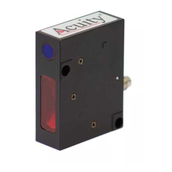
General Description The AR500 is an ultra-compact laser diode-based distance measurement sensor with available ranges covering 5 to 1000 mm. Consult the AR500 data sheet for exact model range availabilities. The accuracy is generally specified with an absolute linearity of +/- 0.10% of the span and a resolution of 0.01% of the span. -
Page 12: Installation
2.3 Installation The AR500 sensor unit is typically installed by affixing the sensor to a machined bracket with bolts through the two mounting holes on the side of the sensor. Their location is shown in the mechanical drawing in section Error! Reference source not found.. -
Page 13: Sensor Maintenance
2.5 Sensor Maintenance The AR500 sensor and module require little maintenance from the user. The sensor lens should be kept clean of dust buildup as a part of regular preventative maintenance. Use compressed air to blow dirt off the windows or use delicate tissue wipes. -
Page 14: Installation And Checkout
Installation and Checkout 3.1 Mounting Mount the sensor in such a way that the case not twisted or warped. Do not clamp or squeeze the sensor case excessively. If the case is distorted, the sensitivity and accuracy of the sensor may be affected. 3.2 Cabling for sensor unit The AR500 sensor has a multipurpose cable with 8 conductors (included). -
Page 15: Serial Connection To A Host Computer
The simplest way to connect the AR500 sensor to a PC computer for initial configuration or regular distance measuring is with the use of an Acuity Connectivity Kit. This is a sealed connection box which contains terminal blocks for each wire lead. It also has an AC power supply and a 2m RS232 serial cable for connection to a PC. -
Page 16: Signal And Power Interface
Signal and Power Interface 4.1 Sensor Cable, Wire Colors and Functions The AR500 sensor includes a multipurpose cable (sensor cable) with solder tail wires. Connection and termination according to the instructions is essential for correct sensor operation. Read the wire descriptions for connection information. -
Page 17: Analog Output (Blue, Grey)
See Serial Interface Operation (section) for information on commands and data. The maximum baud rate is 460.8 KBaud for RS232 and 921.6 KBaud for RS485. RS232: RS232 is normally used for shorter distances of communications and slower data rates. RS232 allows only one transmitter and one receiver per network. -
Page 18: Current Loop
4.4.1 Current Loop Figure 3 The current loop connection scheme is shown in the . The value of load resistor should not be higher than 500 Ohms. To reduce noise, it is recommended to install RC (resistor / capacitor) filter before the measuring instrument. -
Page 19: Logic Outputs (Pink, Grey)
4.5 Logic Outputs (Pink, Grey) The Pink wire is a multi-purpose logic output / interface that can operate in four distinct modes. The functionality can be configured according to the instructions in section 7 . Functions include distance alarms, multi-sensor synchronization, setting of Zero Point via hardware control and control of the laser ON / OFF state. -
Page 20: Serial Interface Operation
Serial Interface Operation This section refers to serial communication protocols for both the Sensor and Module versions of the AR500. 5.1 Communications Protocol and Syntax Serial port communication is required to configure the AR500 for operation. The easiest way to communicate is by using a PC with an RS232 communication port and a terminal emulation program that uses hexadecimal binary format. -
Page 21: Answer
higher tetrad. When multi-byte values are transferred, the transmission begins with the lower byte. The following is the format of two ‘message’ data bursts for transmission of byte: DAT(7:0) Byte 0 Byte 1 DAT(3:0) DAT(7:4) 5.1.3 Answer "Answer’’ is data burst that can be transmitted by a ‘slave’ in the course of the session. -
Page 22: Data Stream
When working with the parameters, it should be noted that when the power is OFF, the parameter values are stored in nonvolatile FLASH- memory of the sensor. When power is ON, the parameter values are read out to RAM of the sensor. To retain these changes for the next power-up state, a special command for saving current parameter values in the FLASH-memory (04h) must be run. -
Page 23: Analog Output Operation
Analog Output Operation AR500 sensors can be ordered with either 4-20mA or 0–10 V analog outputs. The analog outputs use the same two wires. Please refer to Section 4.4 for connection details. The analog output is updated with each sample measured. The analog output will deliver a current which increases linearly from 4 mA (or 0 volts) at the range beginning point to 20 mA (10 volts) at the range end point. - Page 24 0Fh – High byte for the END of the analog output range. Default value is 4000h. Value range: 0 - 4000h. This code specifies a point within the sensor’s span Where: the analog output has a maximum value. AR500 User’s Manual LLL00xxxx –...
-
Page 25: Logic Interface(S) Operation (02H Bits M1 And M0)
Logic Interface(s) Operation (02h bits M1 and M0) All AR500 sensors include a multi-purpose logic line. See the wiring description in section 4.5. This line can work in one of the four modes defined by the configuration parameter of parameter 02h Distance Alarm: This is the default logic output. -
Page 26: Performance Optimization
Performance Optimization This section describes how to configure the AR500 sensor for best use in your particular application. 8.1 Baud Rate (04h) AR500 automatically begins measuring outputting distance measurements to the analog and serial lines when powered-up. The default baud rate is 9600 bit/s. Users may select among several baud rates that will optimize the sensors’... -
Page 27: Sampling Mode (02H Bit S)
Parameter 18h is the HIGH byte of the Zero Point and has values 0 - 4000h with default value 0. 8.5 Sampling Mode (02h bit S) The AR500 has two sampling modes, Time or Trigger Sampling. The factory default setting is Time Sampling. The sensor must be in Data Stream Mode. -
Page 28: Output Rate
taken into account in the case Where: small sampling period intervals are used. If the transmission time exceeds the sampling period, it is this time that will determine the data transmission rate. 8.6.1 Output Rate The sensor’s output rate (OR) depends on the selected Baud rate (BR) of serial interface and is calculated by the following formula: OR = 1 / (44/BR+1*10 ) Hz. -
Page 29: Results Averaging Mode (02H Bit M)
8.9 Results Averaging Mode (02h bit M) This parameter defines one of the two methods of averaging of measurement results implemented directly in the sensor: Averaging over a Number of Results or Time Averaging. The factory default setting is for Averaging over a Number of Results. -
Page 30: Demo And Configuration Software
9. Demo and Configuration Software The AR500-SP software is intended for making simple serial (or Ethernet, if ordered) connections to the AR500 for demonstration purposes and configuration of the many sensor parameters. It is also possible to archive measurement data to a file using this software. -
Page 31: Sensor Operation
If the selected parameters correspond to the parameters of the sensor interface, the program will identify the sensor, read and display its configuration parameters: If connection a connection cannot be established, a prompt will appear asking to make an automatic search for the sensor. -
Page 32: Display And Archiving Of Data
Pressing the Stream button will switch the sensor to the data stream trans- mission mode (07h request code). Move the target object and observe changes in the distance readings. The status line in the lower part of the window will show current data transmission and refreshing rates. -
Page 33: Setting And Saving Sensor Parameters
Additionally, one can manipulate the chart image, press the mouse wheel for movement or rotating the mouse wheel for zooming capabilities. To save measurement data to a file, press the Export button. The program will offer saving of data in two possible formats: internal or Excel. To scan or look at previously saved data, press the Import button and select the required file. -
Page 34: Saving Parameters
9.5.2 Saving Parameters After setting one or more parameters as required, users must write them into the sensor memory. Write parameter by clicking File >Write parameters or by clicking the button. Be sure to perform testing of the sensor operation with the new parameters. -
Page 35: Software Development Kit (Sdk) Descriptions
10. Software Development Kit (SDK) Descriptions The AR500 Laser sensor is supplied together with an SDK consisting of: dynamic library RF60x.dll file for static linking of DLL to project RF60x.lib, Definition file RF60x.h. The SDK allows user to develop his / her own software applications without going into details of the sensor communications protocol. -
Page 36: Device Identification (Rf60X_Hellocmd)
10.3 Device identification (RF60x_HelloCmd) The function RF60x_HelloCmd makes identification of RF60x according to net address and fills RF60xHELLOANSWER structure: typedef struct _RF60x_HELLO_ANSWER_ { BYTE bDeviceType; BYTE bcDeviceModificaton; WORD wDeviceSerial; WORD wDeviceMaxDistance; WORD wDeviceRange; RF60xHELLOANSWER, *LPRF60xHELLOANSWER; Where: – one byte value, which shows type of the device bDeviceType (for RF60x this value is equal 60) (type BYTE);... -
Page 37: Reading Of Parameters (Rf60X_Readparameter)
10.4 Reading of parameters (RF60x_ReadParameter) The function RF60x_ReadParameter reads internal parameters of the RF603 sensor and returns the current value to the parameters address: BOOL RF60x_ReadParameter ( hCOM HANDLE bAddress, BYTE wParameter WORD lpdwValue DWORD * Parameters: hCOM – descriptor of the device obtained from function RF60x_OpenPort, or CreateFile;... -
Page 38: Saving Current Parameters In Flash-Memory (Rf60X_Flushtoflash)
10.5 Saving current parameters in FLASH-memory (RF60x_FlushToFlash) Function RF60x_FlushToFlash saves all parameters in the FLASH-memory of the RF603 sensor: BOOL RF60x_FlushToFlash( hCOM, HANDLE BYTE bAddress Parameters: hCOM – descriptor of the device obtained from function RF60x_OpenPort or CreateFile; bAddress - address of the device. Returned value: If the device does not respond to request to save all parameters in the FLASH- memory, the function returns FALSE, otherwise, if record confirm is obtained... -
Page 39: Get Measurement Result (Rf60X_Measure)
Parameters: hCOM – descriptor of the device obtained from function RF60x_OpenPort or CreateFile; bAddress - address of the device. Returned value: If the device does not respond to result-latching request, the function returns FALSE, otherwise the function returns TRUE. 10.8 Get Measurement Result (RF60x_Measure) The function RF60x_Measure reads current measurement value from the RF603 sensor. -
Page 40: Stop Measurement Stream (Rf60X_Stopstream)
If the device fails to be switched to continuous measurement transmission mode, the function returns FALSE, otherwise the function returns TRUE. 10.10 Stop Measurement stream (RF60x_StopStream) The function RF60x_StopStream switches the sensor from continuous measurement transmission mode to the “request-response” mode: BOOL RF60x_StartStream( hCOM, HANDLE... -
Page 41: Transmission Of User Data (Rf60X_Customcmd)
10.12 Transmission of user data (RF60x_CustomCmd) The function RF60x_CustomCmd is used for transmission and/or reception of data from in RF603 sensor. BOOL RF60x_CustomCmd( hCOM, HANDLE pcInData, char * DWORD dwInSize, pcOutData, char * pdwOutSize DWORD * Parameters: hCOM – descriptor of the device obtained from function RF60x_OpenPort or CreateFile;... -
Page 42: Port Open For Receiving Data Through Ethernet
10.14.1 Port open for receiving data through Ethernet The function RF60x_Ethernet_OpenPort opens net port, fills in the pointer to the device descriptor and returns the operation result: BOOL RF60x_Ethernet_OpenPort ( lpHandle HANDLE * Parameters: lpHandle - pointer to the device descriptor; Returned value: If net-port fails to be opened and/or adjusted, the function will return FALSE, otherwise if net-port was opened and adjusted successfully the... - Page 43 rf60xValArray –168 structures (measurements) RF60xUDPVALUE, which contain measurement and status word; wDeviceSerial –two byte value which contains serial number of the device (type WORD); wDeviceBaseDistance –two byte value which contains base distance of the device (type WORD); wDeviceMeasureRange –two byte value which contains...
- Page 44 If there are no data in the buffer, the function returns FALSE, otherwise the function returns TRUE and fills the structure lprf60xUDPPacket. AR500 User’s Manual LLL00xxxx – Rev 1.0...
-
Page 45: Serial Command Quick Reference
11. Serial Command Quick Reference Request Description Message Answer code (size in bytes) (size in bytes) — –device type (1) Device identification –firmware release (1) –serial number (2) –base distance (2) –range (2) Reading of parameter - code of parameter (1) - value of parameter —... - Page 46 10 – hardware zero set mode 11 – laser turn OFF/ON bit R: 0 – window mode (default); 1 – full range. bit S: 0 – time sampling (default) 1 – trigger sampling. 1…127 (default — 1) Network address 1…192, (default — 4) specifies data transfer rate in Rate of data transfer through serial port increments of 2400 baud;...
- Page 47 byte of extended identifier byte of standard identifier 1 — extended identifier; CAN interface identifier 0 — standard identifier . 1 — CAN interface ON; CAN interface ON/OFF 0 — CAN interface OFF. by default — FFFFFFFFh = 255.255.255.255 0th byte of Destination IP Address byte of Destination IP Address...
-
Page 48: Examples Of Communication Sessions
12. Examples of communication sessions See section 5.1 for descriptions of protocols and section 11 for the codes themselves. 12.1 Request "Device identification". Condition: device address —1, request code –1h, device type — 61, firmware release — 88 (58h), serial number — 0402 (0192h), base distance — 80mm (0050h), measurement range —... -
Page 49: Request: "Reading Of Parameter
Base distance: DAT(7:0) Byte 0 Byte 1 DAT(7:0) Byte 0 Byte 1 Measurement range: DAT(7:0) Byte 0 Byte 1 DAT(7:0) Byte 0 Byte 1 Note: as burst number =1, then CNT=1 12.2 Request: "Reading of parameter". Condition: device address —1, request code – 02h, code of parameter — 05h, value of parameter —... - Page 50 Message ("Master") – 89h, 80h, 80h, 83h and for lower byte, code of parameter – 08h, value of parameter – 39h Request ("Master") – 01h, 83h Message ("Master") – 88h, 80h, 89h, 83h AR500 User’s Manual LLL00xxxx – Rev 1.0...
-
Page 51: Accessories
13. Accessories 13.1 Protective Enclosure Acuity offers an air-cooled, protective housing for the AR500. It is designed to be used in harsher environments of higher ambient temperature or airborne particles. The temperature of compressed air at the sensor input must be °... -
Page 52: Spray Guard
13.2 Spray Guard The optional spray guard is designed to minimize the amount of dirt or liquid spray from reaching the optical windows of the sensor. Figure 9 Spray Guard AR500 User’s Manual LLL00xxxx – Rev 1.0...
Need help?
Do you have a question about the AccuRange AR500 Series and is the answer not in the manual?
Questions and answers