Endress+Hauser SpectraSensors SS2100 Safety Manual
Tdl gas analyzer
Hide thumbs
Also See for SpectraSensors SS2100:
- Operating instructions manual (128 pages) ,
- Operator's manual (114 pages) ,
- Operating instruction (98 pages)
Table of Contents
Advertisement
Quick Links
XA02253C/62/EN/03.20
4900002253 Rev C
Products
Safety Manual
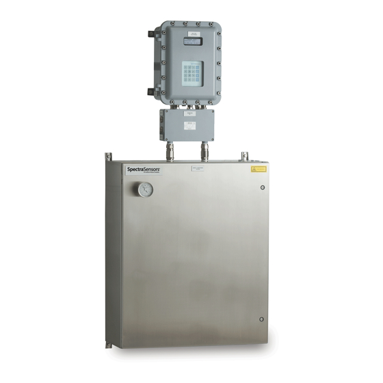
SS2100 TDL Gas Analyzer
Class I, Div.2 Grp. A, B, C, D T3 / T3C
Class I, Zone 2 IIC T3 / T3C
Type 4X, IP66
Copyright © 2020 SpectraSensors, Inc. No part of this manual may be reproduced in
whole or in part without the express written permission of SpectraSensors, Inc.
SpectraSensors reserves the right to change product design and specifications at any
time without prior notice.
Solutions
Services
Advertisement
Table of Contents

Related Manuals for Endress+Hauser SpectraSensors SS2100


Summary of Contents for Endress+Hauser SpectraSensors SS2100
- Page 1 Products Solutions Services XA02253C/62/EN/03.20 4900002253 Rev C Safety Manual SS2100 TDL Gas Analyzer Class I, Div.2 Grp. A, B, C, D T3 / T3C Class I, Zone 2 IIC T3 / T3C Type 4X, IP66 Copyright © 2020 SpectraSensors, Inc. No part of this manual may be reproduced in whole or in part without the express written permission of SpectraSensors, Inc.
-
Page 3: Table Of Contents
ABLE OF ONTENTS List of Figures/Tables ........iii 1: Introduction How to Use This Manual. - Page 4 SS2100 Analyzer Replacing the Filter ......... 5-6 Replacing the scrubber and scrubber efficiency indicator.
- Page 5 IST OF IGURES ABLES FIGURES Figure 4–1. Keypad for CSA-certified analyzers ..... . . 4-2 Figure 4–2. Keypad for ATEX-certified analyzers ..... . 4-2 Figure 5–1.
- Page 6 SS2100 Analyzer THIS PAGE INTENTIONALLY LEFT BLANK 4900002253 rev. C 9-30-20...
-
Page 7: How To Use This Manual
1 - I NTRODUCTION SpectraSensors’ SS2100 products are high-speed, diode-laser based extractive analyzers designed for extremely reliable monitoring of very low (trace) to standard concentrations of specific components in various background gases. In order to operate the analyzer safely, it is important to closely review all information contained in this manual. -
Page 8: Spectrasensors Overview
Headquartered in Houston, Texas, SpectraSensors was incorporated in 1999 as a spin-off of the NASA/Caltech Jet Propulsion Laboratory (JPL) for the purpose of commercializing space-proven measurement technologies initially developed at JPL. SpectraSensors was acquired by the Endress+Hauser Group in 2012. Manufacturer Address SpectraSensors, Inc. -
Page 9: 2: General Safety Information
2 - G ENERAL AFETY NFORMATION This chapter reviews the general safety instructions for every SS2100 analyzer. Intended Equipment Use The SS2100 analyzer is intended for use as instructed in the documentation package provided with the equipment. SpectraSensors recommends that the qualified technician read and reference the documentation when installing, operating or having direct contact with the SS2100 analyzer. -
Page 10: Equipment Labels
SS2100 Analyzer Hazards may vary by stream composition. One or more of the following conditions may apply. Flammable. Gases used in the processing of this analyzer may be extremely flammable. Any work in a hazardous area must be carefully controlled to avoid creating any possible ignition sources (e.g., heat, arcing, sparking, etc.). -
Page 11: Instructional Symbols
General Safety Information FUNCTIONAL EARTH GROUND - Symbol indicates grounding points intended primarily for troubleshooting. INVISIBLE LASER RADIATION - Avoid CAUTION exposure to beam. Class 3b Radiation Product. CLASS 3B INVISIBLE LASER Refer servicing to the manufacturer or qualified RADIATION WHEN OPEN personnel. -
Page 12: Analyzer Technical Specifications
SS2100 Analyzer Analyzer Technical Specifications Refer to Equipment ratings for specifications related to the SS2100 analyzer. Peripheral devices For systems equipped with peripheral devices, e.g., probe assemblies, refer to documentation provided by the manufacturer for instruction on installation, operation, etc. Equipment ratings Equipment rating information for the SS2100 analyzer is included in Table 2-1 below. -
Page 13: Potential Risks Affecting Personnel
General Safety Information Table 2-1 SS2100 analyzer equipment ratings and specifications (Continued) Application Data Environmental Temperature –20 C to 50 C (–4 F to 122 F) Range/Sample Cell Temperature –10 C to 60 C (14 F to 140 F) - Optional Range Environmental Relative 5% to 95%, Non-condensing... -
Page 14: Personnel Responsibility
SS2100 Analyzer potential hazards within this document. The user is responsible for identifying and mitigating any potential hazards present when servicing the analyzer. Personnel Responsibility The safety of the analyzer is the responsibility of the installer and the organization he/she represents. Mitigating risks Refer to the instructions for each situation listed below to mitigate associated risks. -
Page 15: Explosion/Fire Hazard
General Safety Information Explosion/fire hazard Any work in a hazardous area must be carefully controlled to avoid creating any possible ignition sources (e.g., heat, arcing, sparking, etc.). All tools must be appropriate for the area and hazards present. Electrical connections must not be made or broken with power on (to avoid arcing). - Page 16 SS2100 Analyzer THIS PAGE INTENTIONALLY LEFT BLANK. – 4900002253 rev. C 9-30-20...
-
Page 17: Mounting The Analyzer
3 - E QUIPMENT NSTALLATION The information in this chapter is related to safety during the equipment installation. SpectraSensors Class 1 Division II analyzers use a non-incendive protection method, and as such all portions of the local installation codes apply. The maximum allowed inductance to resistance ratio (L/R ratio) for the field wiring interface must be less than 25 µH/Ω. -
Page 18: Electrical Wiring Requirements
SS2100 Analyzer conduit runs. Always carry the load using one of the following points/methods (refer to the drawings included with the purchased SS2100 analyzer model): • Mounting points on Unistrut frame • Cross members on Unistrut frame • Support beneath instrument (best used when employing a forklift) Ensure all equipment used for lifting/moving the analyzer is rated for the weight load. -
Page 19: Protective Chassis And Ground Connections
Equipment Installation A switch or circuit breaker must not interrupt a protective earth conductor. Thread lubricant must be applied on all conduit hub threaded connections. SpectraSensors recommends using STL8 lubricant on all conduit screw thread and it’s taped openings. Protective Chassis and Ground Connections Before connecting any electrical signal or power, the protective and chassis grounds must be connected. -
Page 20: To Connect The Sample Supply Line
SS2100 Analyzer Process samples may contain hazardous material in potentially flammable and/or toxic concentrations. Personnel should have a thorough knowledge and understanding of the physical properties and safety precautions for the sample contents before installing the SCS. SpectraSensors recommends using 1/4” O.D x 0.035” wall thickness, seamless stainless steel tubing. -
Page 21: Ventilation Requirements
Equipment Installation 6. Fully ream all tubing ends. Blow out the line for 10 to 15 seconds with clean, dry nitrogen or air prior to making the connection. 7. Connect the sample supply tube to the SCS using the 1/4” stainless steel compression-type fitting provided. - Page 22 SS2100 Analyzer THIS PAGE INTENTIONALLY LEFT BLANK. – 4900002253 rev. C 9-30-20...
-
Page 23: 4: Equipment Operation
4 - E QUIPMENT PERATION This chapter provides an overview of safety operational instructions for the SS2100 analyzer. Firmware Version Each SpectraSensors analyzer operates based on its own version of firmware. The firmware version for each analyzer is listed in the system calibration report, and displays upon start-up of the analyzer. -
Page 24: Figure 4-1 Keypad For Csa-Certified Analyzers
SS2100 Analyzer EXPONENT VALUE LCD (DISPLAY) SCROLL DIRECTION AND ANALOG INPUT ENTER KEY TEST MODE MENU SCRUBBER LIFE TEST MODE ENTER DATA CHANGE ACTIVATE PROCESS PARAMETERS DIAGNOSTICS EXPORT PARAMETERS DIAGNOSTIC DATA ACTIVATE VALIDATION 1 VALIDATION RESULTS ACTIVATE ANALOG OUTPUT VALIDATION 2 TEST Figure 4–1 Keypad for CSA-certified analyzers CHANGE... -
Page 25: Intermittent Operation
Equipment Operation Intermittent Operation To isolate the measurement cell for short‐term shutdown The analyzer can be isolated from the primary sample bypass section for short- term shutdown or maintenance of the analyzer while allowing the sample bypass flow to continue in a steady-state mode. Due to the high pressure of the process sample, it is advisable to allow the sample bypass flow to continue during short-term isolation of the analyzer. - Page 26 SS2100 Analyzer Although the pressure reducing regulator at the process sample tap is designed for “bubble-tight” shut off, this condition may not occur after the system has been in operation for an extended period. Isolation of the SCS from the field pressure regulator will discontinue sample flow and may cause the pressure at the outlet of the field pressure regulator to slowly increase if “bubble-tight”...
-
Page 27: 5: Maintenance And Service
5 - M AINTENANCE AND ERVICE This chapter provides safety information for the maintenance and service of the SS2100 analyzer. Potentially Hazardous Substances SS2100 analyzers that detect H S can acquire leaks that lead to unsafe amounts of toxic gas. Refer to “Mitigating risks” on page 2-6. Disposal of hazardous substances Depleted H S scrubbers and scrubber indicators contain... -
Page 28: To Prevent Electrostatic Discharge
SS2100 Analyzer To prevent electrostatic discharge 1. Use a damp cloth to clean the displays to avoid static electricity discharge. Replacement Parts All parts required for operation of the SS2100 analyzer must be supplied by SpectraSensors or an authorized agent. Refer to Service Contact for contact information to determine specific parts listing for the purchased model. - Page 29 Maintenance and Service Table 5-1 Fuse specifications (Continued) Drawing Reference Voltage Description Rating 1 Solenoid, Miniature Fuse, 250 VAC 5 x 20 mm, Time Delay 0.25 A 2 Solenoid, Miniature Fuse, 250 VAC 5 x 20 mm, Time Delay 0.4 A Figure 24 VDC 5–2...
-
Page 30: Replacing A Fuse
SS2100 Analyzer FUSE (F2) FUSE (F1) Figure 5–2 H S analyzer electronics control board (DC) showing fuses Replacing a Fuse 1. Power off the system and close the sample supply valve. 2. Open the electronics enclosure. Refer to Figure 5–1 (AC) or Figure 5–2 (DC) for fuse location 3. -
Page 31: Figure 5-3 Unscrewing Fuse Cover
Maintenance and Service FUSE COVER Figure 5–3 Unscrewing fuse cover FUSE Figure 5–4 Replacing fuse 6. Insert the new fuse into the screw cover and replace into the fuse opening. 7. Use the screwdriver to turn the fuse cover clockwise until tight. Do not overtighten. -
Page 32: Replacing The Membrane Separator
SS2100 Analyzer Replacing the Membrane Separator Use the following steps to replace a membrane separator. 1. Close the sample supply valve. 2. Unscrew the cap from the membrane separator. If the membrane filter is dry: 3. Check if there are any contaminants or discoloring of the white membrane. -
Page 33: Replacing The Scrubber And Scrubber Efficiency Indicator
Maintenance and Service 9. Place the filter unit into the analyzer and tighten the base with the four screws. 10. Check upstream of membrane for liquid contamination and clean and dry out before opening the sample supply valve. 11. Check connections for gas leaks. SpectraSensors recommends using a liquid leak detector. -
Page 34: Disposal Of Used Scrubbers
SS2100 Analyzer 4. Tighten all new fittings 1-1/4 turns with a wrench from finger tight. For connections with previously swaged ferrules, thread the nut to the previously pulled up position, then tighten slightly with a wrench. 5. Reset the scrubber lifetime monitor with the New Scrub Installed parameter and the General Fault Alarm with the Reset option for the General Alarm parameter (see “To change parameters in... -
Page 35: Service Repair Order
All returns should be shipped to: SpectraSensors, Inc. An Endress+Hauser Company 11027 Arrow Rte. Rancho Cucamonga, CA 91730-4866 United States of America 1-909-948-4100 –... - Page 36 SS2100 Analyzer THIS PAGE INTENTIONALLY LEFT BLANK – 4900002253 rev. C 9-30-20...
- Page 37 XA02253C/62/EN/03.20 4900002253 Rev C www.spectrasensors.com/contact...
Need help?
Do you have a question about the SpectraSensors SS2100 and is the answer not in the manual?
Questions and answers