
Related Manuals for Ossila DIP COATER


Summary of Contents for Ossila DIP COATER
- Page 1 DIP COATER USER MANUAL Manual Version: 1.0.C Product Code: L2006A1 Product Version: 1.0 Software Version: 1.2...
-
Page 2: Table Of Contents
5. Specifications ........................11 6. System Components ......................12 7. Installation ..........................12 8. Operation ..........................13 8.1 Dip Coater Diagram ........................13 8.2 Dip Coater User Interface ......................14 8.3 Practical Operation .........................15 8.4 Program Operation ........................16 8.5 Operational Safety ..........................35 9. Maintenance .........................35 9.1 Cleaning .............................35 10. -
Page 3: Overview
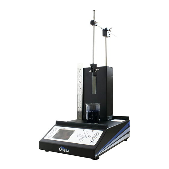
The Ossila Dip Coater’s wide working base means that larger beakers (up to 2 litres in size) can be used. As the movement distance of the arm is 110mm, you can coat substrates over 100mm in length. Its clamping mechanism uses a simple spring-loaded clamp for easy substrate removal. -
Page 4: Eu Declaration Of Conformity (Doc)
Telephone number: +44 (0)114 2999 180 Email Address: info@ossila.com declare that the DoC is issued under our sole responsibility and belongs to the following product: Product: Dip Coater (L2006A1) Serial number: L2006A-1000-1000-1000- xxxx Object of declaration: Dip Coater (L2006A1) The object of declaration described above is in conformity... - Page 5 хармонизиране, посочено на предходната(-ите) страница(-и) на настоящия документ. [Čeština] Prohlášení o shodě EU Výrobce: Ossila Ltd., Solpro Business Park, Windsor Street, S4 7WD, Spojené Království Prohlašujeme na vlastní odpovědnost, že uvedené zařízeni je v souladu s příslušnými harmonizačními předpisy EU uvedenými na předchozích stranách tohoto dokumentu.
- Page 6 [Por tuguês] Declaração de Conformidade UE Fabricante: Ossila Ltd., Solpro Business Park, Windsor Street, S4 7WD, Reino Unido Declara sob sua exclusiva responsabilidade que o equipamento indicado está em conformidade com a legislação de harmonização relevante da UE mencionada na(s) página(s) anterior(es) deste documento.
-
Page 7: Safety
Temperatures of 5°C to 40°C; maximum relative humidity of 80% up to 31°C. The Dip Coater is supplied with a 24VDC power adapter with a power cord for the country of purchase, (in accordance with European Commission regulations and British Standards). The use of any other electrical power cables, adaptors, or transformers is not recommended. -
Page 8: General Hazards
3.4 General Hazards Before installing or operating the Dip Coater, there are several health and safety precautions which must be followed and executed to ensure safe installation and operation. WARNING: Improper handling when operating or servicing this equipment can result in serious injury. -
Page 9: Crash-Detection Switch
Examine the components for any evidence of shipping damage. If damage has occurred, please contact Ossila directly for further action. The shipping box comes with a shock indicator to show if there has been mishandling of the package during transportation. -
Page 10: Specifications
5. Specifications The Dip Coater specifications are shown in Table 5.1. and Table 5.2. Table 5.1. Dip Coater specifications. Dip Coater Feature Specifications Travel Length 100 mm Minimum Speed 0.01 mm.s ; 0.6mm.min Maximum Speed 50 mm s ; 3000 mm.min Positional Reproducibility 0.01%... -
Page 11: System Components
Keep the area surrounding the machine clear, with approximately 150 mm clearance above the machine, to the sides of the machine, and behind the machine. Before plugging in the Dip Coater, ensure the power switch on the unit is switched to the ‘0’ position (off). -
Page 12: Operation
Figure 7.2. Installation of the Dip Coater by plugging in the power supply cable. 8. Operation 8.1 Dip Coater Diagram An isometric view of Dip Coater is shown in Figure 8.1, with all the relevant components highlighted. Figure 8.1. Dip Coater schematic. -
Page 13: Dip Coater User Interface
8.2 Dip Coater User Interface Figure 8.2 shows the front panel of the Dip Coater, where the function of each of the keypad buttons is explained in Table 8.1. Figure 8.2. Dip Coater LCD screen and keypad. Dip Coater Coating... -
Page 14: Practical Operation
The position of the dipping arm can be adjusted to be nearer or further away from the user by loosening the arm adjustment screw. Ensure that there is a distance of at least 1 cm from the edge of the baseplate of the Dip Coater. 8.3.3 Adjusting Clamp Strength Pull back one half of the clamp and insert a substrate, being sure to provide support in case the clamp strength is not yet high enough. -
Page 15: Program Operation
8.4 Program Operation 8.4.1 Dip Coater Start Up Switch ON (position ‘1’) the Ossila Dip Coater power switch. The screen below will be shown. After the Ossila logo page, reset the arm to the ‘Home’ position by pressing the OK button. - Page 16 Once the system is at the ‘Home’ position, the ‘Settings Mode’ page will be prompted. 8.4.2 Settings Mode To enter ‘Settings’ mode, press the S button (located at the top left-hand side of the screen). To edit the coating length value, press the OK button, then navigate between the digits by pressing either the left or right button.
- Page 17 To navigate to ‘Substrate Position’, press the down button and then OK to edit the value. Press the left or right button to navigate between the digits and press the up or down button to increase or decrease the selected digit. Press OK again to exit the edit mode. To navigate to ‘Solution Height’, press the down button and then OK to edit the value.
- Page 18 Note: A warning message will appear if the difference between substrate position and solution height plus coating length and drying gap is more than the maximum travel distance (100 mm). Note: A warning will appear if the substrate position is set below the solution height.
- Page 19 Press the up or down button to increase or decrease the value. Press OK again to exit the edit mode. The maximum drying gap is 50 mm, and the default value is 5 mm. Note: The default ‘Drying Gap’ is 5 mm. The value will reset every time the Dip Coater is switched OFF.
- Page 20 Note: The maximum travel distance of the system is 100 mm. Any increases in coating length value (in (Step 2.) and Drying Gap should be within this maximum travel distance. The coating length will be auto-corrected if the added value is more than 100 mm. To navigate to a previous page, press the down button until ‘Back’...
- Page 21 8.4.3 Manual Mode To enter ‘Manual Mode’, press the M button on the left-hand side of the screen. To set the immersion speed, navigate to ‘Immersion speed’ and press OK to edit the value. To change the value, press the left or right button to navigate between the digits, and press the up or down button to increase or decrease the selected digit.
- Page 22 To operate the clamping arm, press the left button to select the diagram on the screen. Then, press the up or down button to move the arm based on the set speed. Note: The maximum travel distance is 100 mm. Alternatively, you can move the clamping arm with a single speed for up-and-down motion.
- Page 23 To set the Free speed, press OK to enter edit mode. To change the value, press the left or right button to navigate between the digits and press the up or down button to increase or decrease the selected digit. Press OK again to exit the edit mode. To operate the clamping arm, press the left button to select the diagram on the screen.
- Page 24 8.4.4 Program Mode To enter ‘Program Mode’, press the P button on the left-hand side of the screen. To set the program number, navigate by pressing the up button, then press OK to enter edit mode. To change the value, press the up or down button and press OK again to exit edit mode. Note: The maximum number of programs is 20.
- Page 25 To set the number of cycles, navigate to ‘Cycle’ by pressing the down button and press OK to enter edit mode. To change the value, press the left or right button to navigate between the digits, and press the up or down button to increase or decrease the selected digit. Press OK again to exit the edit mode.
- Page 26 To set the immersion speed, navigate to ‘Dip Speed’ by pressing the down button, and press OK to enter edit mode. To change the value, press the left or right button to navigate between the digits, and press the up or down button to increase or decrease the selected digit. Press OK again to exit the edit mode.
- Page 27 To set the ‘Dwell Time’, navigate to it by pressing the down button, then press the OK button to enter edit mode. To change the value, press the left or right button to navigate between the digits, and press the up or down button to increase or decrease the selected digit. Press OK again to exit the edit mode.
- Page 28 a.) Unit in mm/min b.) Unit in mm/min...
- Page 29 To set the final withdrawal speed, navigate to ‘Final Speed’ by pressing the down button, and press the OK button to enter edit mode. To change the value, press the left or right button to navigate between the digits, and press the up or down button to increase or decrease the selected digit. Press OK again to exit the edit mode.
- Page 30 10. To return to the immersion page, navigate to ‘Immersion’ at the bottom of the screen until it is highlighted in yellow, then press OK. 11. Once the all the values have been set, press the START button to run the program.
- Page 31 Once the coating cycle has been completed, the following message will appear: Note: A warning will appear if any of the conditions below occur. a) Operation has been stopped by pressing the STOP button.
- Page 32 b) Immersion – Dip speed not set. c) Withdrawal – Initial speed not set. d) Withdrawal – Final speed not set.
- Page 33 e.) When the maximum travel distance exceeds 100 mm a warning will be given. f.) Crash detected between substrate and other hard surface (e.g. beaker or base of the case).
-
Page 34: Operational Safety
8.5 Operational Safety Any procedure that is done with the Dip Coater should be carried out with a suitable operating procedure, risk assessment, and COSHH forms to ensure that the user knows and understands the potential hazards inherent to the system of work they are undertaking. The following are safety points that should be noted by the user before any procedure is undertaken with the Dip Coater. -
Page 35: Troubleshooting
10. Troubleshooting Table 10.1. Troubleshooting guidelines for the Ossila Dip Coater Problem Possible cause Action No power / display a.) The power switch on the unit is in Check the connection and ensure the the OFF position power is turned ON b. -
Page 36: Related Products
11. Related products 11.1 Compatible Substrates PV and OLED ITO Scale-Up OFET ITO Scale-Up Substrates Substrates A 25 x 75 mm ITO patterned glass A 25 x 75 mm version of our popular substrate, available with either module interdigitated ITO substrates for OFET or pixelated design.
Need help?
Do you have a question about the DIP COATER and is the answer not in the manual?
Questions and answers