Table of Contents
Advertisement
Contents
...1
1.1 Daily Maintenance...................................................................3
1.2 Periodic Maintenance................................................................5
1.3 Maintenance Interval ...............................................................6
1.4 Maintenance Contents ..........................................................10
1.5 Replacement of Oil and Oil Filter .............................................13
1.6 Replace Fuel Filter ..............................................................16
1.7 Check Air Filter Element ..........................................................17
1.8 Check and Adjust Valve Clearance ...........................................19
1.9 Check and Adjust Fuel Supply Advance Angle .............................24
..................................................................................26
2.1 Assemble Injection Nozzle, Camshaft and Cylinder Liner...............26
2.1.1 Assemble Injection Nozzle ..................................................26
2.1.2 Assemble Camshaft ...........................................................26
2.1.3 Assemble Cylinder Liner ....................................................27
2.2 Pre-assemble & Assemble Crankshaft .......................................29
2.2.1 Assembling Steps (1) .........................................................29
2.2.2 Assembling Steps (2) .........................................................30
2.3 Assemble Cylinder Body .......................................................31
2.4 Pre-assemble & Assemble Connecting Stick and Piston ...............32
2.5 The Assembly of the Timing Gear Housing .................................36
2.6 The Assembly of Flywheel Housing and Flywheel ........................39
2.6.1 The Assembly of Flywheel Housing .......................................39
2.6.2 The Assembly of Flywheel ..................................................39
Engine .....................................................................................42
...44
3.1 Diesel Engine Starts Hard .......................................................44
Advertisement
Table of Contents


Need help?
Do you have a question about the WD615 and is the answer not in the manual?
Questions and answers
Nesecito distribución motor 615
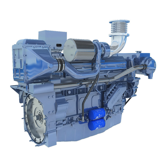
The WEICHAI WD615 engine is used in various applications including marine, automotive, construction, agriculture, and power generation. Specifically, it is used in heavy-duty trucks and mining vehicles such as:
- Vehicle-XG80, XG90
- Weichai mining vehicle-tank 90, tank 95
- Sxtongyun mining vehicle
- Guerte mining vehicle
- Shaanxi Shacman F3000
- Sinotruk Howo A7
It features a 6-cylinder, turbocharged intercooler design, with different models offering rated power from 266 to 410 horsepower at 2200 rpm.
This answer is automatically generated
Сколько нужно антифриза на систему охлаждения двигателя
Hola quiero regular balbula de motor wp12 420e32
Здравствуйте! А можно где-то найти нумерацию последовательности болтов пртяжки головок блоков цилиндров на двигатель wd618 c17, в общем по номерам какой за каким болт и вспомогательные гайки закручивать
Oil thrower torque