WEICHAI WP13GTA Assembly/Disassembly Manual
Hide thumbs
Also See for WP13GTA:
- Operation and maintenance manual (33 pages) ,
- Installation and application manual (25 pages)

Related Manuals for WEICHAI WP13GTA


Summary of Contents for WEICHAI WP13GTA
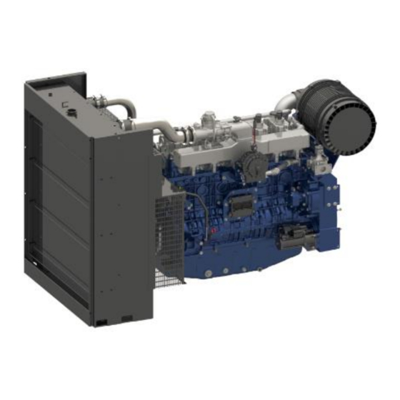
- Page 1 Document Courtesy of Fly Parts Guy Co. www.FlyPartsGuy.com Assembly & Disassembly Manual Gas Engine Model: WP13GTA WEICHAI AMERICA CORP.
- Page 2 Weichai America Corp. Purpose This manual is intended to inform customers on how to assemble and disassemble the Weichai America 13 Liters turbocharged engine. This document will be provided to customer so they can incorporate this information into their manuals and service documents.
-
Page 3: Table Of Contents
Document Courtesy of Fly Parts Guy Co. www.FlyPartsGuy.com Weichai America Corp. Table of Contents Disassembly & Assembly of Engine ..................5 1.1 Safety Precautions ......................5 1.2 Environmental Protection Measures ................. 5 1.3 Notes for Disassembly and Assembly of Engine ............... 5 Engine block assembly ...................... - Page 4 Document Courtesy of Fly Parts Guy Co. www.FlyPartsGuy.com Weichai America Corp. 5.5 Valve removal and installation ..................47 5.6 Intermediate gear disassembly and assembly ..............49 Intake and Exhaust System ....................50 6.1 Air filter combination group dismantling and assembly ............ 50 6.2 Intake pipe combination group disassembly and assembly ..........
- Page 5 Document Courtesy of Fly Parts Guy Co. www.FlyPartsGuy.com Weichai America Corp. APPENDIX A ......................82...
-
Page 6: Disassembly & Assembly Of Engine
Document Courtesy of Fly Parts Guy Co. www.FlyPartsGuy.com Weichai America Corp. 1 Disassembly & Assembly of Engine Safety Precautions Please strictly comply with instructions in this manual to safely and properly disassemble and assemble the engine. Environmental Protection Measures Please comply with relevant laws and regulations on environmental protection when handling oil and hydrocarbon waste. -
Page 7: Engine Block Assembly
Document Courtesy of Fly Parts Guy Co. www.FlyPartsGuy.com Weichai America Corp. 2 Engine block assembly Disassembly and assembly of engine block assembly 2.1.1 Exploded view of engine block assembly 1. Engine block 2. Cylinder liner 3. Pin 4. Gasket 5. Hex head bolt 6. Hexagon socket head cap screws 7. -
Page 8: Steps To Assemble And Disassemble Engine Block Module
Document Courtesy of Fly Parts Guy Co. www.FlyPartsGuy.com Weichai America Corp. housing, gear housing and oil pan 2.1.3 Dismantling 1. Remove the crankcase around the bolt; 2. Remove the main bearing bolts; 3. Remove the seal; 4. Remove the main oil duct plug;... - Page 9 Document Courtesy of Fly Parts Guy Co. www.FlyPartsGuy.com Weichai America Corp. 1.Cylinder block 2. Internal thread cylindrical pin 3. Camshaft bushings 4. Rear camshaft bushing 5. Main bearing bolts 6. Crankcase 7. Bowl plug 8. Bowl plug Fig. 2- 2 Exploded View of Engine Block Module 2.2.2 Preparation before disassembly...
-
Page 10: Front Cover Disassembly And Assembly
Document Courtesy of Fly Parts Guy Co. www.FlyPartsGuy.com Weichai America Corp. 2.2.5 Service Key point 1. Disassembly: Use special tools to disassemble the camshaft bushing, pay attention to protect the other bushing during disassembly; 2. Assembly: Before assembly, carefully check the inner surface of the camshaft bush for scratches, replace if necessary. - Page 11 Document Courtesy of Fly Parts Guy Co. www.FlyPartsGuy.com Weichai America Corp. 1 front cover 2 Pin 3 Hex flange bolts Figure 2-4 Exploded view of front cover 2.3.2 Preparation before disassembly 1. Equipment conditions: Socket wrench 2. Preparation before disassembly: Remove the front attachment 2.3.3 Dismantling...
-
Page 12: Assembly And Disassembly Of Flywheel Housing
Document Courtesy of Fly Parts Guy Co. www.FlyPartsGuy.com Weichai America Corp. the seal must be pressed fully into the front cover groove. Assembly and disassembly of flywheel housing 2.4.1 Exploded view of flywheel housing 1. Flywheel shell 2. Hexagon flange bolts to increase the series 3. Hex flange bolts to increase the series 4. -
Page 13: Assembly And Disassembly Of Piston Nozzle
Document Courtesy of Fly Parts Guy Co. www.FlyPartsGuy.com Weichai America Corp. 2. Remove the observation hole cover fastening bolt, remove the observation hole cover; 3. Remove the flywheel housing stud along the outside; 4. Remove the flywheel housing fastening bolt according to the diagonal loosening sequence;... -
Page 14: Assembly And Disassembly Of Thrust Plates
Document Courtesy of Fly Parts Guy Co. www.FlyPartsGuy.com Weichai America Corp. 2.5.2 Preparation before disassembly 1. Equipment conditions: Socket wrench 2. Preparation before disassembly: Remove the crankcase, crankshaft and other components. 2.5.3 Dismantling 1. Remove the hollow bolt; 2. Remove the nozzle assembly;... -
Page 15: Assembly And Disassembly Of Oil Seal
Document Courtesy of Fly Parts Guy Co. www.FlyPartsGuy.com Weichai America Corp. 1. Cylinder block 2. Crankcase 3. Upper thrust plate 4. Lower thrust plate Figure 2-7 Thrust piece dismantling map 2.6.2 Preparation before disassembly 1. Equipment conditions: Socket wrench 2. Preparation before disassembly: Remove the crankcase, crankshaft and other components. - Page 16 Document Courtesy of Fly Parts Guy Co. www.FlyPartsGuy.com Weichai America Corp. 1. Body combination group 2. Front cover 3. Flywheel housing 4. Rear oil seal 5. Front oil seal Figure 2-8 Oil seal dismantling map 2.7.2 Preparation before disassembly 1. Equipment conditions: Socket wrench 2.
-
Page 17: Cylinder Head Group
Document Courtesy of Fly Parts Guy Co. www.FlyPartsGuy.com Weichai America Corp. 3 Cylinder Head Group Cylinder Heads Assembly and Disassembly 3.1.1 Preparation before disassembly 1. Equipment conditions: Socket wrench 2. Preparation before disassembly: Remove the cylinder head cover, intake pipe, exhaust pipe. - Page 18 Document Courtesy of Fly Parts Guy Co. www.FlyPartsGuy.com Weichai America Corp. 2. Loosen the cylinder head bolt and nut, and remove the clamping block, clamping block has three structures: one is mounted between the two cylinder head cylindrical clamping block, mounted on a bolt;...
- Page 19 Document Courtesy of Fly Parts Guy Co. www.FlyPartsGuy.com Weichai America Corp. 3) Clean the threaded hole on the cylinder body; 4) Tighten the bolts, tightening torque: (20+10) N · m. 2. Assemble cylinder head gasket Figure 3-2 Cylinder head gasket 1) Cylinder head gasket can only be used once, in case of repair, you must replace the new parts;...
- Page 20 Document Courtesy of Fly Parts Guy Co. www.FlyPartsGuy.com Weichai America Corp. Valve stem gland installation tools Valve stem gland Installation direction Valve guide Cylinder head Figure 3-3 Valve stems gland and its installation and installation 4. Assemble the cylinder head 1) Carefully clean the cylinder head, to ensure that no dust, debris, sand and other dirt, and then wipe the cylinder head plane;...
- Page 21 Document Courtesy of Fly Parts Guy Co. www.FlyPartsGuy.com Weichai America Corp. 2) In order, align the cylinder head with the cylinder head and cylinder head bolt and clamping block with appropriate amount of clean lubricant on the thread and shoulder pressure surface of the main cylinder head bolt and shoulder nut;...
- Page 22 Document Courtesy of Fly Parts Guy Co. www.FlyPartsGuy.com Weichai America Corp. 3.1.5 Cylinder head inspection and maintenance 1. Before removing the cylinder head cover first check cylinder head and body joints with no water leakage, oil leakage, air leaks and other abnormal phenomena. If any such problems, replace the new cylinder head gasket to see if the problem is solved, the cylinder head gasket disassembly method, see this section.
- Page 23 Document Courtesy of Fly Parts Guy Co. www.FlyPartsGuy.com Weichai America Corp. the gas generator. If the valve does not sink more than the allowable value, remove the valve check valve and valve seat sealing surface, check valve and valve seat sealing surface for obvious wear and tear and abnormal damage.
-
Page 24: Disassembly And Assembly Of Cylinder Head Cover
Document Courtesy of Fly Parts Guy Co. www.FlyPartsGuy.com Weichai America Corp. 9. Before disassembling, check the valve stem seal rubber sleeve mouth for any damage, spring failure and other anomalies. Disassembly and assembly of cylinder head cover 3.2.1 Preparation before disassembly 1. -
Page 25: Oil And Gas Separator Dismantling And Assembly
Document Courtesy of Fly Parts Guy Co. www.FlyPartsGuy.com Weichai America Corp. 4. Remove cylinder head cover and cylinder head cover gasket vertically. 3.2.4 Cylinder head cover assembly steps 1. Before installing the cylinder head cover gasket Check the new cylinder head gasket does not manufacture and use defects and damage. - Page 26 Document Courtesy of Fly Parts Guy Co. www.FlyPartsGuy.com Weichai America Corp. 3.3.2 Oil and gas separator assembly disassembly diagram 1-oil and gas separator bracket; 2-hexagonal flange bolts; 3-combination gasket; 4- screw structure; 8 Clamp 9 Oil return pipe 10 Clamp 11 Oil and gas separator 12 Hex flange bolt 13 Clamp 14 Intake...
-
Page 27: Lifting Lugs Assembly And Disassembly
Document Courtesy of Fly Parts Guy Co. www.FlyPartsGuy.com Weichai America Corp. inlet pipe; 5. Remove the oil and gas separator fixing bolts 12, remove the oil and gas separator; 6. Remove the oil and gas separator bracket fixing bolt 2, Remove the oil and gas separator bracket. - Page 28 Document Courtesy of Fly Parts Guy Co. www.FlyPartsGuy.com Weichai America Corp. 1- rings; 2-shoulder nut; 3-rings clamping block Figure 3-9 Lifting Lugs Exploded View 3.4.2 Lifting Lugs Disassembly Procedure Loosen and remove the lifting lugs. 3.4.3 Lifting Lugs Assembly Procedure Check the lifting lugs and standoffs for any damaged threads.
-
Page 29: Crank-Rod Mechanism
Document Courtesy of Fly Parts Guy Co. www.FlyPartsGuy.com Weichai America Corp. 4 Crank-rod mechanism Main bearing bolts Crankcase Connecting rod cover Main bearing assembly Oil pump gear Shock absorbers bolts Gasket Torsional vibration damper Crankshaft pulley 10. Hex head bolt 11. -
Page 30: Flywheel, Flywheel Gear Ring, Flywheel Connection Plate Removal And Installation
Document Courtesy of Fly Parts Guy Co. www.FlyPartsGuy.com Weichai America Corp. 1. Equipment conditions: torque wrench 2. Preparation before disassembly: Removed fan, belt, tensioner and other parts 4.1.3 Dismantling 1. Unscrew the pulley bolt (1) and remove the pulley assembly. - Page 31 Document Courtesy of Fly Parts Guy Co. www.FlyPartsGuy.com Weichai America Corp. 1. Crankshaft 2. Pin 3. Flywheel shell 4. Crankshaft timing gear 5. Pin 6. Ring gear 7. Flywheel 8. connection plate 9. Connecting bolt 10. Flywheel bolts Figure 4-3 Exploded view 4.2.2 Preparation before disassembly...
-
Page 32: Crankshaft Bearing Disassembly And Assembly
Document Courtesy of Fly Parts Guy Co. www.FlyPartsGuy.com Weichai America Corp. assembly and tighten the flywheel bolt diagonally (10). 4.2.6 Maintenance points 1. Lubricate the bolt thread and pressure surface. 2. The flywheel bolts are special bolts M16 × 1.5. After the flywheel bolts are installed diagonally, the torque is 105 (0, + 20) Nm, then rotate two 90 °... -
Page 33: Crankshaft Removal And Installation
Document Courtesy of Fly Parts Guy Co. www.FlyPartsGuy.com Weichai America Corp. 2. If there is no new bearing, the assembly should be loaded into the body (upper tile) and the crankcase (lower tile) in the order of the time when the original bearing was removed, pay attention to distinguish the upper and lower tiles and the upper tile with the oil groove;... - Page 34 Document Courtesy of Fly Parts Guy Co. www.FlyPartsGuy.com Weichai America Corp. 1. With the engine crankcase (7) facing up, remove the main bearing bolts (8) and place them in order to lift the crankcase (7). 2. Lift the crankshaft (4), remove the front and rear thrust washers (2, 6); place the crankshaft on the bracket (if placed too long, the crankshaft should be placed vertically).
- Page 35 Document Courtesy of Fly Parts Guy Co. www.FlyPartsGuy.com Weichai America Corp. 5-1, should ensure that the cylinder block with a clean and burr-free. 6. Clean with a detergent and wipe the bottom hole of the cylinder main bearing with a towel, then press the main bearing on the tile (3) into the bottom hole.
-
Page 36: Piston Rod Group Disassembly And Assembly
Document Courtesy of Fly Parts Guy Co. www.FlyPartsGuy.com Weichai America Corp. Figure 4-6 Main bearing bolt tightening order 13. The first time with a low torque pneumatic wrench tighten; the second reached 80N · m; the third reached 140N · m; the fourth order of 90 ° and finally turn 60° to finish assembly. - Page 37 Document Courtesy of Fly Parts Guy Co. www.FlyPartsGuy.com Weichai America Corp. Figure 4-7 Exploded view 4.5.2 Preparation before disassembly 1. Equipment conditions: socket wrenches, pneumatic wrenches, wooden hammer and hole ring clamp 2. Disassembly Preparation: Fixed cylinder block and tilt, with a pneumatic wrench to unscrew the connecting rod bolts, remove the cover.
- Page 38 Document Courtesy of Fly Parts Guy Co. www.FlyPartsGuy.com Weichai America Corp. ring should be inward and the retaining ring opening should be offset 30 ° from the centerline of the piston. As shown in Figure 4-8 The collar opening is offset 30 °...
- Page 39 Document Courtesy of Fly Parts Guy Co. www.FlyPartsGuy.com Weichai America Corp. openings are staggered by 120 ° and at the perpendicular bisector of the centerline of the piston pin. As shown in Figure 4-9 Figure 4-9 Piston ring assembly opening angle diagram 6.
-
Page 40: Valve Train
Document Courtesy of Fly Parts Guy Co. www.FlyPartsGuy.com Weichai America Corp. 3. Check the piston ring cylindrical wear is abnormal; check the piston ring upper and lower face wear is abnormal; 4. Check the piston pin cylindrical wear is abnormal;... - Page 41 Document Courtesy of Fly Parts Guy Co. www.FlyPartsGuy.com Weichai America Corp. 1. Gear chamber 2. Hex head bolt 3. Camshaft timing gear 4. Hexagon head bolt 5. Throttle 6. Camshaft assembly 7. Intake valve 8. Cylinder head 9 , Valve lifter; 10, putter; 11 valve spring;...
-
Page 42: Camshaft Disassembly And Assembly
Document Courtesy of Fly Parts Guy Co. www.FlyPartsGuy.com Weichai America Corp. 3. Assembly into the exhaust valve, see the intake and exhaust valve assembly steps; Assembly rocker and rocker shaft, see rocker and rocker shaft assembly steps. Camshaft disassembly and assembly 5.2.1 Exploded view... - Page 43 Document Courtesy of Fly Parts Guy Co. www.FlyPartsGuy.com Weichai America Corp. timing gear hex head bolt (1) and remove the timing gear (2). 5. Remove the camshaft thrust plate hex head bolt (3), remove the thrust plate (4), remove the camshaft assembly (5).
-
Page 44: Rocker And Rocker Shaft Removal And Installation
Document Courtesy of Fly Parts Guy Co. www.FlyPartsGuy.com Weichai America Corp. camshaft timing gear is punctured or has serious wear on the tooth surface. Point 2: Assembly 1) If it is found bump camshaft bump, do not allow repair use;... - Page 45 Document Courtesy of Fly Parts Guy Co. www.FlyPartsGuy.com Weichai America Corp. 2. Measure the valve clearance, check the valve clearance change. 3. Loosen the hexagon head bolts (6) if the rocker is not rotating properly or the valve clearance is greatly changed, then gently remove the rocker arm assembly (5), rocker arm assembly (4) and rocker bracket ), Well marked, so as not to confuse each cylinder rocker.
-
Page 46: Tappet And Putter Removal And Installation
Document Courtesy of Fly Parts Guy Co. www.FlyPartsGuy.com Weichai America Corp. dead center (33 ± 5) °, exhaust valve to open before the deadline (49 ± 5) °. 5.3.5 Maintenance points Point 1: Check after demolition 1) The rocker clean, observe the appearance of the rocker, whether there are cracks and other defects. - Page 47 Document Courtesy of Fly Parts Guy Co. www.FlyPartsGuy.com Weichai America Corp. 1. Equipment conditions: tappet installation tools, lubricants. 2. Disassembly Preparation: After the cylinder head cover is disassembled, loosen the rocker shaft assembly to fix the hex head bolt, and then remove the push rod (4). After the cylinder head is disassembled, remove the tappet (2).
-
Page 48: Valve Removal And Installation
Document Courtesy of Fly Parts Guy Co. www.FlyPartsGuy.com Weichai America Corp. Point 2: Assembly The valve tappet (2) the outer surface of the cylinder and the bottom of the clean oil, oil evenly; The push rod (4) coated with clean oil, you must ensure that the ball and the Au have enough lubricant;... - Page 49 Document Courtesy of Fly Parts Guy Co. www.FlyPartsGuy.com Weichai America Corp. 1. If the valve is worn or carbon soot serious sintering and other undesirable phenomena, the need for valve replacement. 2. The molybdenum disulfide paste evenly coated on the exhaust valve stem, and then into the exhaust valve (1) (6) into the cylinder head to ensure that the intake and exhaust valve sliding in the catheter without block;...
-
Page 50: Intermediate Gear Disassembly And Assembly
Document Courtesy of Fly Parts Guy Co. www.FlyPartsGuy.com Weichai America Corp. Intermediate gear disassembly and assembly 5.6.1 Exploded view 1. Hexagon head bolt 2. Intermediate gear shaft 3. Intermediate gear assembly 4. Idler baffle 5. Flywheel housing connecting plate 6. Camshaft timing gear 7. Body Figure 5-6 Exploded view 5.6.2 Preparation before disassembly... -
Page 51: Intake And Exhaust System
Document Courtesy of Fly Parts Guy Co. www.FlyPartsGuy.com Weichai America Corp. hexagon head bolts ) And tighten. 5.6.5 Maintenance points Point 1: Check the mounting bolt mark before disassembly to confirm whether the bolt is rotating or not; Point 2: Check the mounting bolt thread before assembly is good, the gear shaft bolt bearing surface is crushed;... - Page 52 Document Courtesy of Fly Parts Guy Co. www.FlyPartsGuy.com Weichai America Corp. 1, air filter; 2, air filter bracket; 3 & 9, hexagonal flange bolt; 4 & 8, clamp; 5, adapter; 6, pressure sensor 7, intake manifold Figure 6-1 Exploded view 6.1.2 Preparation before disassembly...
-
Page 53: Intake Pipe Combination Group Disassembly And Assembly
Document Courtesy of Fly Parts Guy Co. www.FlyPartsGuy.com Weichai America Corp. Intake pipe combination group disassembly and assembly 6.2.1 Exploded view 1 & 2 & 9, hexagonal flange bolts; 3, gasket; 4, flat washers; 5, spring washers; 6, hexagonal head cap screws; 7, mixed intake manifold; 8, pressure and temperature sensors; ; 10, connector;... -
Page 54: Exhaust Pipe Disassembly And Assembly
Document Courtesy of Fly Parts Guy Co. www.FlyPartsGuy.com Weichai America Corp. Assembly and disassembly steps on the contrary, intake pipe bolts recommended tightening torque 23N · m. 6.2.5 Maintenance points 1. Check the intake manifold for cracks, deformation and other damage, if you need to replace the new intake manifold. - Page 55 Document Courtesy of Fly Parts Guy Co. www.FlyPartsGuy.com Weichai America Corp. Figure 6-3 Exploded view Preparation before disassembly 1. Equipment conditions: pneumatic wrench, sleeve 2. Prepare for disassembly: Disassemble and disassemble the peripheral parts around the group 6.3.2 Dismantling The disassembly sequence is the opposite of the installation sequence.
-
Page 56: Turbocharger Dismantling And Assembly
Document Courtesy of Fly Parts Guy Co. www.FlyPartsGuy.com Weichai America Corp. 6. Exhaust system bolts, nuts are made of heat-resistant steel, do not use ordinary bolts and nuts instead. Turbocharger dismantling and assembly 6.4.1 Exploded view 1, the supercharger into the pipe assembly; 2, the hexagonal head cap screws; 3, the waveform elastic washers;... - Page 57 Document Courtesy of Fly Parts Guy Co. www.FlyPartsGuy.com Weichai America Corp. 6.4.3 Dismantling Disassembly steps are the opposite of assembly steps. 6.4.4 Installation 1. Assemble the turbocharger (22), booster gasket (5) and spacer (7) with the studs (6) and hex nuts (8) and tighten them with a wrench.
-
Page 58: Mixed Intake System With The Disassembly And Assembly Of The Group
Document Courtesy of Fly Parts Guy Co. www.FlyPartsGuy.com Weichai America Corp. 7. Wipe off the impeller channel with gasoline, grease on the housing cavity. 8. When reinstalling the compressor scroll case, tighten the fastening screws as required and tighten the torque 15N.m. - Page 59 Document Courtesy of Fly Parts Guy Co. www.FlyPartsGuy.com Weichai America Corp. 6.5.3 Dismantling The disassembly sequence is the opposite of the installation sequence. 6.5.4 Installation 3. Fit the temperature and pressure transducer (5) to the mixing inlet manifold (3) with the hex head bolt (4) and tighten with a wrench.
-
Page 60: Cooling System
Document Courtesy of Fly Parts Guy Co. www.FlyPartsGuy.com Weichai America Corp. 3. Check the pressure and temperature sensors for burnout, short circuit and so on, if there is need to be replaced. 7 Cooling system Cooling system disassembly and assembly 7.1.1 Exploded view... -
Page 61: Fan Dismantling And Assembly
Document Courtesy of Fly Parts Guy Co. www.FlyPartsGuy.com Weichai America Corp. 3. Remove the pump. 4. Remove the thermostat. 7.1.4 Installation The reverse order of disassembly. 7.1.5 Installation 1. Assembly: Tightening torque according to standard; 2. Assembly: Before the assembly should be carefully checked to see if there are cracks and clean the various components;... -
Page 62: Pump Disassembly And Assembly
Document Courtesy of Fly Parts Guy Co. www.FlyPartsGuy.com Weichai America Corp. 2. Remove the six bolts and nuts that secure the fan shaft. 7.2.4 Installation 1. Loosen the fan drive shaft with the six hexagon head bolts on the fan bracket and tighten. -
Page 63: Thermostat Dismantling And Assembly
Document Courtesy of Fly Parts Guy Co. www.FlyPartsGuy.com Weichai America Corp. 1. Polishing the front of the cylinder block and the back surface of the pump cover, and wipe the glue. The combination of pump back cover and cylinder block coated with 518 plane sealants. - Page 64 Document Courtesy of Fly Parts Guy Co. www.FlyPartsGuy.com Weichai America Corp. First unscrew the thermostat cover, the thermostat into the pump, and then placed in 2 O-ring fitted thermostat cover and tightened. 7.4.5 Maintenance points Check thermostat and seal for damage, if damaged, you need to replace the new one.
-
Page 65: Lubrication System
Document Courtesy of Fly Parts Guy Co. www.FlyPartsGuy.com Weichai America Corp. 8 Lubrication system Lubrication system dismantling and assembly 8.1.1 Exploded view 1. Oil Filter 2. Oil Cooler Cover 3. Oil Gauge 4. Set Filter 5. Oil Pump 6. Oil Cooler 7. Oil Cooler Cover 8. -
Page 66: Oil Filter Dismantling And Assembly
2. Pre-installed weld to be checked whether there is a crack or leak welding, set filter assembly. Set the filter thread of the fastening bolt Weichai special 242 sealant, separated by a wave... -
Page 67: Oil Pump Disassembly And Assembly
Document Courtesy of Fly Parts Guy Co. www.FlyPartsGuy.com Weichai America Corp. washer screwed hex bolts and tighten. 8.2.5 Maintenance points 1. Check the filter for cracks and other damage, the cavity is smooth, if you need to replace the filter set. -
Page 68: Oil Filter, Oil Filter Seat Disassembly And Assembly
Document Courtesy of Fly Parts Guy Co. www.FlyPartsGuy.com Weichai America Corp. 8.3.5 Maintenance points 1. Check the oil pump for cracks and other damage, check the oil pump drive gear is flexible, 2. If the rotation is not flexible or there is a need to replace the broken oil pump. -
Page 69: Oil Cooler Cap Disassembly And Assembly
Document Courtesy of Fly Parts Guy Co. www.FlyPartsGuy.com Weichai America Corp. Oil cooler cap disassembly and assembly 8.5.1 Exploded view 1. Oil cooler cover 2. Washer 3. Plug 4. Hex flange bolt 5. Support block Figure 8-5 Exploded view 8.5.2 Preparation before disassembly 1. -
Page 70: Oil Cooler Disassembly And Assembly
Document Courtesy of Fly Parts Guy Co. www.FlyPartsGuy.com Weichai America Corp. Oil cooler disassembly and assembly 8.6.1 Exploded view 1. O-ring 2. Oil cooler 3. Hex bolts Figure 8-6 Exploded view 8.6.2 Preparation before disassembly 1. Equipment conditions: Socket wrench 2. -
Page 71: Oil Pan Disassembly And Assembly
Document Courtesy of Fly Parts Guy Co. www.FlyPartsGuy.com Weichai America Corp. Oil pan disassembly and assembly 8.7.1 Exploded view 1. Gasket 2. Oil pan 3. Support block 4. Hex flange bolt Figure 8-7 Exploded view 8.7.2 Preparation before disassembly 1. Equipment conditions: Socket wrenches, special tooling 2. - Page 72 Document Courtesy of Fly Parts Guy Co. www.FlyPartsGuy.com Weichai America Corp. tightening torque is 22N · m ~ 29N · m. Figure 8-8 tighten the oil pan fastening bolts...
-
Page 73: Start The System
Document Courtesy of Fly Parts Guy Co. www.FlyPartsGuy.com Weichai America Corp. 9 Start the system Startup system disassembly and assembly 9.1.1 Exploded view Starting system consists of a starter and a fixed starter stud, nut composition. 1, stud, 2, starter, 3, nut Figure 9-1 Exploded view 9.1.2 Dismantling... -
Page 74: Gas System
Document Courtesy of Fly Parts Guy Co. www.FlyPartsGuy.com Weichai America Corp. 10 Gas system 10.1 Ignition system disassembly and assembly 10.1.1 Exploded view 1- Hexagon socket head cap screw; 2-Gasket; 3-Ignition coil; 4-Spark plug Figure 10-1 Exploded view 10.1.2 Preparation before disassembly Equipment conditions: Spark plug special wrench, sleeve. - Page 75 Document Courtesy of Fly Parts Guy Co. www.FlyPartsGuy.com Weichai America Corp. Figure 10-2 Spark plug special wrench 10.1.4 Installation 1. Tighten spark plug with professional spark plug wrench, tightening torque (25-28) Nm; 2. Assemble the ignition coil, push it down vertically in assembly, do not push and pull laterally;...
-
Page 76: Signal Generator Disassembly And Assembly
Document Courtesy of Fly Parts Guy Co. www.FlyPartsGuy.com Weichai America Corp. 10.2 Signal generator disassembly and assembly 10.2.1 Exploded view Hexagon socket head cap screw; 2- Flat washer; 3- Cover plate; 4-bolt; 5-washer; 6- spring washer; 7. Hexagonal flange bolt; 8-Speed sensor; 9-Signal generator 10 Bolt 11 Washer 12 O-... - Page 77 Document Courtesy of Fly Parts Guy Co. www.FlyPartsGuy.com Weichai America Corp. 3. Install the timing gear on the signal generator, tighten with M20 hex nut, tightening torque (200-220) Nm; 4. Install the speed sensor on the signal generator, tighten the M6 hex flange bolts, tightening torque (8-10) Nm;...
-
Page 78: Electronic Control Module Disassembly And Assembly
Document Courtesy of Fly Parts Guy Co. www.FlyPartsGuy.com Weichai America Corp. 5. Check the clearance between the speed sensor and the gear unit of signal generator, it should be (0.5-1.5) mm. 10.3 Electronic control module disassembly and assembly 10.3.1 Exploded view 1-Hexagon socket head cap screw;... -
Page 79: Lpg Supply System Dismantling And Assembly
Document Courtesy of Fly Parts Guy Co. www.FlyPartsGuy.com Weichai America Corp. 10.3.5 Maintenance points 1. Check if the internal pins of the ECU electrical socket end are abnormal. If there is a failure mode such as pin rusting, bending, breaking, missing, etc., replace the ECU;... -
Page 80: Ng Gas Supply System Dismantling And Assembly
Document Courtesy of Fly Parts Guy Co. www.FlyPartsGuy.com Weichai America Corp. 10.4.3 Dismantling 1. Remove the clamp between the LPG evaporator and the gas pipe and fix the bolt on the flange end of the gas pipe to remove the gas pipe assembly and hose;... - Page 81 Document Courtesy of Fly Parts Guy Co. www.FlyPartsGuy.com Weichai America Corp. 1-solenoid valve; 2-O-ring; 3-gasket; 4-hexagonal flange bolts; 5-hexagonal flange nuts; 6- hose; 7- gas pipe; 8- Hexagonal flange bolt 10 EPR valve 11 mixer 12 bolt 13 spring washer 14 mixer...
- Page 82 Document Courtesy of Fly Parts Guy Co. www.FlyPartsGuy.com Weichai America Corp. 5. Remove the fixing bolt between gas pipe and EPR valve; 6. Remove the clamp at both ends of the hose, remove the gas pipe and hose; 7. Remove the bolts on the EPR valve fixing bracket and remove the bracket;...
- Page 83 Document Courtesy of Fly Parts Guy Co. www.FlyPartsGuy.com Weichai America Corp. 11 APPENDIX A Appendix A: Tolerance Clearance for Main Parts of Gas Engine (Reference value) Items Theoretical value (mm) Main bearing clearance 0.063~0.138 Connecting rod bearing clearance 0.05~0.125 Crankshaft axial clearance 0.052~0.255...
- Page 84 Document Courtesy of Fly Parts Guy Co. www.FlyPartsGuy.com Weichai America Corp. 3100 Golf Road Rolling Meadows, IL 60008 http://www.WeichaiAmerica.com/...
Need help?
Do you have a question about the WP13GTA and is the answer not in the manual?
Questions and answers