Table of Contents
Advertisement
Quick Links
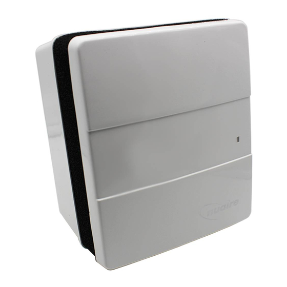
1.0 Genie-DC and DCE fans
Genie-DC and DCE are part of our established Genie range but
with low watt DC mot or s to save energy. The Genie range of
fans has been specifically designed to ventilate small r ooms
such as kitchens, toilets, bathrooms, cloakrooms and similar
and can be surface or r ecessed
* An optional window mounting kit is available for this unit,
code r ef: WINKIT
Air entering the unit passes through a washable filter fitted to the
front cover. Anti-backdraught shutters, retained in the closed
position when fan is not running, are fitted to the base plate
(S and H models only).
Motor has sealed, ball bearings and locked rotor protection.
All units are fitted with high efficiency 12V DC motors. The fan/
motor assembly is retained by spring clips to simplify maintenance.
Interchangeable plug in electronic control modules can incorporate:
■ Run-on timer
■ Humidistat
■ Continuous low duty with boost.
Genie units are supplied with a finishing frame for use in
semi-recessed
applications.
Warning: when installing Genie units for r emote switching it
is important that the pull cord (if fitted) is r emoved.
It is r ecommended that the unit is switched of f (by the pull
cord) before cutting. Cut the pull cord inside the unit a little
way beyond the control module.
1.1 Coding
230V unit
12V unit
GENIE-DC-S
GENIE-DC-S1 2
GENIE-DC-H
GENIE-DC-H12
GENIE-DC-X
GENIE-DC-X12
GENIE-DC-XH
GENIE-DC-XH12
GENIE-DCE
GENIE-DCE-12
GENIE-DCE-H
GENIE-DCE-H12
*light switch or similar or remote switch (by others).
WINKIT = Optional window mounting kit.
1.2 GENIE-DCE
This model is designed to operate in accordance with the
requirements of building regulations 2000 Part F Means of
Ventilation, System 3. (2010 Edition).
They are designed to operate continuously at a low ventilation level.
Sanitary accommodation is not required to be fitted with a fan if it
contains an openable window. For set up instructions please refer
to section 4.
The Genie-DCE units are SAP appendix Q listed. Please refer to
www.sap-appendixq.org.uk for further details.
Nuaire: A Trading Division of Polypipe Limited Western Industrial Estate Caerphilly United Kingdom CF83 1NA
T: 029 2088 5911 F: 029 2088 7033 E: info@nuaire.co.uk W: www.nuaire.co.uk
Genie-DC and DCE
12V and 230V
Universal Surface Mounted Fans
mounted.
Descr iption
With integral run-on
timer, operated by
remote switch* only.
With integral humidistat,
operated by pull cord
or remote switch*
Continuous low duty
with boost facility
operated by pull cord
or remote switch*
Continuous low duty
with boost facility
via internal humidistat
operated by pull cord
See 1.2
See 1.2
System 3 – Continuous mechanical extract (MEV) r equires
that fans be fitt ed in the kitchen and all other wet r ooms
(bathroom, utility r oom, en-suite bathroom).
2.0 Fan Installation
To be carried out by qualified personnel only.
2.1 Surface Mounting
Not e. It is assumed that a solid mounting position has
been select ed and passages
outlet spigot, as well as electrical connection prepared.
In addition that compatible ductwork has been installed.
Figure 1. Surface mounted, wall. NB. Base drill pattern
superimposed on page 6.
Figure 2. Remove cover.
Press tabs to release cover.
Cover screws.
Easy stretch fit removable filter.
clips. Install the electronic control module (Fig. 3) ensuring that it is
fully engaged in the internal socket then insert the plug-in wiring
connector into the electronic control module (Fig 4a).
If the pull-cord option is required it should be fed through the
aperture on the impeller housing before sliding the control module
into place. (see Fig 4b). If the pullcord option is not required it must
be removed. Replace the front cover.
7. Ensure two cover screws are fitted.
8. Fit the filter which is a push fit between the front cover and the
body of the unit (see Fig. 2).
9. Test run the unit noting that if a timer/humidistat option is
fitted, the unit may run-on for the duration of the control sequence.
Isolation - Before commencing work make sure that
the unit is electrically isolated from the mains and
switched live supply.
1
The EMC Directive
2014/30/EU
The Low Voltage
Directive
2014/35/EU
for ductwork fr om the
NB. The discharge spigot is 98mm od.
The hole in the structure should therefore
be of a dimension to accomodate any
ducting or cavity lining used.
1. Remove cover/grille assembly by
removing cover screws. Depress the
top/bottom retaining tabs. (Fig. 2).
2. Unplug the wiring connector
(Fig 4a) from the electronic control
module, then remove the electronic
control module. (Fig. 3).
3. Remove the fan/motor assembly
by pulling aside the two spring clips
(see Fig. 3).
4. Place the unit in the mounting
position, connect the ductwork and
feed the cable through the cable
entry. Connect the wiring to the
terminal block (it may be easier to
temporarily remove the block to
facilitate wiring).
5. Drill and plug the mounting
surface if necessary and secure the
unit in position, using three No. 6
wood screws.
6. Re-fit the fan assembly to the
case, securing it with the two spring
11. 06. 18. Leaflet Number 671504
Advertisement
Table of Contents

Related Manuals for NuAire Genie-DC Series


Summary of Contents for NuAire Genie-DC Series
- Page 1 Nuaire: A Trading Division of Polypipe Limited Western Industrial Estate Caerphilly United Kingdom CF83 1NA T: 029 2088 5911 F: 029 2088 7033 E: info@nuaire.co.uk W: www.nuaire.co.uk 11. 06. 18. Leaflet Number 671504...
- Page 2 Installation and Maintenance Genie DC & DCE 12V & 230V Universal Surface Mounted Fans 2.1 Surface Mounting cont. Figure 4a. Plug-in wiring connector fits into the electronic control module. Figure 3. Unit components. Electronic control module. Fan/motor Pullcord. assembly Plug-in wiring connector.
- Page 3 Installation and Maintenance Genie DC & DCE 12V & 230V Universal Surface Mounted Fans 2.3 Window Mounting Figure 9. The window mounting kit is WINKIT P arts checklist designed for mounting the unit 10mm Front view into windows 4mm to 32mm The WINKIT contains the following parts.
- Page 4 Installation and Maintenance Genie DC & DCE 12V & 230V Universal Surface Mounted Fans 3.0 Genie-DC Commissioning P ower Consump tion 230V 1 2 V Unit input power (watts) a) Run-on-timer Full load current (amps) .085 Starting Current (amps) .085 When installing a unit with Figure 10a.
- Page 5 SELV installations. between tr ansformer and fan. 7.0 Maintenance 8.0 Replacement of P arts Should any component need replacing Nuaire keep extensive stocks General for quick delivery. Ensure that the unit is electrically isolated, before carrying out any work.
- Page 6 Genie DC & DCE 12V & 230V Universal Surface Mounted Fans Figure 13. Genie-DC and DCE base drill pattern. Western Industrial Estate Caerphilly United Kingdom CF83 1NA T: 029 2088 5911 F: 029 2088 7033 E: info@nuaire.co.uk W: www.nuaire.co.uk 11. 06. 18. Leaflet Number 671504...
Need help?
Do you have a question about the Genie-DC Series and is the answer not in the manual?
Questions and answers