Advertisement
Quick Links
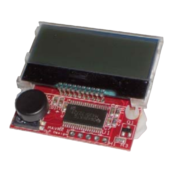
LCD / MICROCONTROLLER MODULE
The DLP-MAV-LCD1 combines a 2x16-character backlit LCD display with a TI MSP430
microcontroller to form a MAVRK-supported display module. The MSP430 is preprogrammed with
basic functionality for driving the LCD display via either the MAVRK platform or a simple, 5-pin TTL
serial interface.
FEATURES:
•
Simple ASCII Command Set
•
Requires 3.0-3.3V Supply
•
LED Backlight
•
5-Switch Joystick (Left, Right, Up, Down and Select)
•
Can Be Used Standalone or with the MAVRK Platform
1.0 GENERAL DESCRIPTION
The DLP-MAV-LCD1 provides the MAVRK platform with a means of displaying data that does not
require a connected host PC.
To send data from the host processor on the MAVRK platform via the 2-wire TTL serial interface, the
host firmware sends the data to be displayed using the format described below in Section 3.
When the 5-switch joystick is operated, the DLP-MAV-LCD1 issues switch closure information to the
host processor using the MAVRK platform protocol. This protocol consists of a printable ASCII format
using a synchronization character "^", and a termination character "~". (This protocol is further
described in Section 3.)
The DLP-MAV-LCD1 is ready to accept commands immediately upon power up. (Initial baud rate and
serial parameters are outlined in Section 3.)
Rev. 1.0 (February 2012)
1
D
L
P
-
M
A
V
D
L
P
-
M
A
V
L
C
D
1
L
C
D
1
LEAD FREE
© DLP Design, Inc.
-
-
Advertisement

Subscribe to Our Youtube Channel
Related Manuals for DLP Design DLP-MAVLCD1


Summary of Contents for DLP Design DLP-MAVLCD1
- Page 1 “^”, and a termination character “~”. (This protocol is further described in Section 3.) The DLP-MAV-LCD1 is ready to accept commands immediately upon power up. (Initial baud rate and serial parameters are outlined in Section 3.) Rev. 1.0 (February 2012) © DLP Design, Inc.
- Page 2 6. Add the following lines in the function main() under the ones you just commented out above: mvk_Configure_UART_Passthrough (MAVRK_UART_P1P2, MAVRK_UART_TUSB); mvk_Configure_UART_Passthrough (MAVRK_UART_TUSB, MAVRK_UART_P1P2); 7. Rebuild the project, and reload the MAVRK platform with your new flash. Rev. 1.0 (February 2012) © DLP Design, Inc.
- Page 3 MAVRK platform until you build and load your new MAVRK platform flash file as described in Section 2.) Alternatively, you can communicate directly with the unit in standalone mode. Troubleshooting information will also be available on the MAVRK wiki pages referenced above. Rev. 1.0 (February 2012) © DLP Design, Inc.
- Page 4 Baud Rate Menu. (Note that this must be done during the first 5 seconds when the splash screen shown above is displayed.) Figure 5: Baud Rate Menu Once Select has been pressed, the Baud Rate Menu (see Figure 5) will be displayed. Rev. 1.0 (February 2012) © DLP Design, Inc.
- Page 5 9600 immediately to continue processing any further commands.) The TTL interface requires the specific formatting described below for all message traffic to and from the LCD: Rev. 1.0 (February 2012) © DLP Design, Inc.
- Page 6 Key Select (Center Down) Select ^kS~ was Pressed Table 4: Key Definitions Keys will be sent to the connected terminal with de-bounce. If you hold the key down longer than 500mS, it will repeat. Rev. 1.0 (February 2012) © DLP Design, Inc.
- Page 7 Once each command has been issued, the next data command will start writing text from this location and will automatically increment to the next location based upon the length of the text string: Rev. 1.0 (February 2012) © DLP Design, Inc.
- Page 8 ^cCC~ ^cCD~ ^cCE~ ^cCF~ Table 6: Cursor Location Definitions The table below describes sample strings sent to the DLP-MAV-LCD1 to include clearing the screen and positioning the cursor prior to writing text: Rev. 1.0 (February 2012) © DLP Design, Inc.
-
Page 9: Standalone Mode
TO EXTERNAL HOST (Out) – TTL serial to host processor GROUND RESET (In) – Pull to ground to reset MSP430 on DLP-MAV-LCD1 3.0 - 3.3V (In) – Power supply for module Table 8: TTL 5-Pin Header Descriptions Rev. 1.0 (February 2012) © DLP Design, Inc. -
Page 10: Mechanical Drawings
This product and its documentation are supplied on an as-is basis, and no warranty as to their suitability for any particular purpose is either made or implied. DLP Design will not accept any claim for damages whatsoever arising as a result of use or failure of this product. Your statutory rights are not affected. -
Page 11: Contact Information
7.0 CONTACT INFORMATION DLP Design, Inc. 1605 Roma Lane Allen, TX 75013 Phone: 469-964-8027 Fax: 415-901-4859 Email Sales: sales@dlpdesign.com Email Support: support@dlpdesign.com Website URL: http://www.dlpdesign.com Rev. 1.0 (February 2012) © DLP Design, Inc.
Need help?
Do you have a question about the DLP-MAVLCD1 and is the answer not in the manual?
Questions and answers