Table of Contents
Advertisement
Available languages
Available languages
Quick Links
Advertisement
Chapters
Table of Contents

Subscribe to Our Youtube Channel
Related Manuals for Riello Multi Switch


Summary of Contents for Riello Multi Switch
-
Page 3: Table Of Contents
GENERAL DESCRIPTION OF THE SYSTEM ......................... 4 2.1 Load distribution ..............................4 2.2 Interventions................................4 INSTALLATION ................................6 SAFETY GUIDELINES ..............................7 STRUCTURE OF THE MULTI SWITCH ........................8 DISPLAY ..................................9 INTERFACING ................................. 10 7.1 Serial port RS232 ..............................10 7.2 Communicatio Slot ............................... 10 USAGE AND OPERATING CONDITIONS ........................ -
Page 4: Introduction
GENERAL DESCRIPTION OF THE SYSTEM The Multi Switch unit has been designed to allow you to install and manage eight users from a single point, using one or two power supply lines, either direct from the mains power supply or served by an UPS. - Page 5 - ENGLISH - ________________________________________________________________________________________________________ Block diagram of the Multi Switch So that it will operate when at least one of the two lines “A” or “B” is present, the power supply is redundant. Relays RL1, RL2, RL3, RL4, RL5, RL6, RL7, RL8 switch the output loads from line A to line B, whilst relays RL9,...
-
Page 6: Installation
INSTALLATION Remove the machine from its packaging with caution. Attach the handles to the side of the Multi Switch with the appropriate screws. Assemblage of the handles Install upstream of the apparatus a 16A magneto-thermal switch with intervention curve B or C. -
Page 7: Safety Guidelines
________________________________________________________________________________________________________ The Multi Switch measures the shift between the two power supply lines “A” and “B” and, whenever this shift exceeds 11 degrees, displays an alarm message on the LCD display. It is important when installing the machine to ensure that the two lines “A”... -
Page 8: Structure Of The Multi Switch
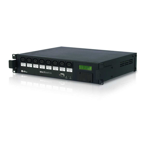
- ENGLISH - ________________________________________________________________________________________________________ STRUCTURE OF THE MULTI SWITCH The Multi Switch has two male IEC power supply input sockets on the rear and eight female IEC output sockets on the front. Front and rear view of the Multi Switch The Multi Switch is equipped with an expansion slot (COMMUNICATION SLOT) for accessory communication boards. -
Page 9: Display
LCD display indicates this on the status/alarm line as shown in figure (c) and (d). The shift reading is given in multiples of 11. LCD display The Multi Switch does not emit any acoustic alarm. Presence of an alarm is indicated solely on the LCD display. -
Page 10: Interfacing
OMMUNICATIO You can use the optional network card NetMan 204 to monitor the staus of the "Multi Switch". The Netman 204 has to be inserted in the Communication Slot. In this case it is necessary to set the slide switch on the SLOT side. -
Page 11: Usage And Operating Conditions
Avoid knocking or bumping the casing as this might cause damage to the mechanical and electrical components of the machine. Do not place other items on top of the Multi Switch if the total combined weight is five (5) times greater than the machine itself. -
Page 12: Warranty
10 WARRANTY The Multi Switch is covered by a guarantee valid from the date it was bought. The guarantee does not include equipment that is used incorrectly, or is modified due to circumstances external to the machine or to force major, is repaired by third parties, or if the serial number has been removed or modified. - Page 13 2.1 Distribuzione dei carichi ............................14 2.2 Interventi ................................14 ISTRUZIONI PER L’INSTALLAZIONE ......................... 16 PRECAUZIONI PER LA SICUREZZA ........................... 17 STRUTTURA DEL MULTI SWITCH ..........................18 Descrizione DISPLY ..............................19 DESCRIZIONE INTERFACCIAMENTO ........................20 7.1 Porta seriale RS232 ............................. 20 7.2 Communication Slot .............................
-
Page 14: Introduzione
DESCRIZIONE GENERALE DEL SISTEMA Il Multi Switch, è stata progettata per consentire la distribuzione e la gestione da remoto di otto utenze in un sistema con una o due linee di alimentazione dirette o asservite da UPS. - Page 15 - ITALIANO - ________________________________________________________________________________________________________ Schema a blocchi del Multi Switch L’alimentatore è ridondato in modo da funzionare quando è presente almeno una delle due linee “A” o “B”. I relè RL1, RL2, RL3, RL4, RL5, RL6, RL7, RL8 garantiscono la commutazione dalla linea A alla linea B del carico di ogni uscita mentre i relè...
-
Page 16: Istruzioni Per L'installazione
Per maggior sicurezza e per evitare di effettuare connessioni sbagliate, utilizzare i cavi di alimentazione forniti con la macchina. Le configurazioni possibili delle alimentazioni del Multi Switch sono illustrate nella figura seguente. La configurazione (a) è la migliore in termini di: ... -
Page 17: Precauzioni Per La Sicurezza
________________________________________________________________________________________________________ Il Multi Switch misura lo sfasamento tra le due linee di alimentazione “A” e “B” e, nel caso in cui lo sfasamento superi gli 11 gradi, viene visualizzato un messaggio di allarme sul display LCD. E’ pertanto necessario verificare che all’atto dell’installazione le due linee “A”... -
Page 18: Struttura Del Multi Switch
________________________________________________________________________________________________________ STRUTTURA DEL MULTI SWITCH Il Multi Switch è fornito di due prese di ingresso di tipo IEC maschio per l’alimentazione poste sul retro e otto prese di uscita di tipo IEC femmina, poste sul frontale. Fronte e retro del Multi Switch Il Multi Switch è... -
Page 19: Descrizione Disply
LCD ne da indicazione sulla riga di stato/allarmi, come mostrato in figura (c) e (d). L’indicazione dello sfasamento è un multiplo di 11. Esempi di visualizzazioni Per quanto riguarda gli allarmi, il Multi Switch non fornisce alcun tipo di segnalazione acustica ma solo informazioni tramite il display LCD. -
Page 20: Descrizione Interfacciamento
ORTA SERIALE Per utilizzare la porta seriale RS232, posizionare il selettore a slitta sul lato RS232. La porta seriale consente di connettere il Multi Switch direttamente ad un PC, per il monitoraggio e la configurazione del Multi Switch tramite protocollo proprietario. -
Page 21: Condizioni Di Impiego E Funzionamento
NOTA: Queste istruzioni possono essere modificate dalle norme di cablaggio in vigore localmente per ogni Nazione. Funzionamento Il Multi Switch è stato progettato per funzionare soltanto in ambienti chiusi. È bene installarlo in ambienti privi di liquidi infiammabili, gas o altre sostanze nocive. -
Page 22: Garanzia
10 GARANZIA Il Multi Switch è coperto da una garanzia dalla data di acquisto: la garanzia non si riferisce a prodotti che siano stati utilizzati in modo sbagliato, modificati per cause di forza maggiore o esterne al prodotto, riparate da terzi, o se il numero di serie è... - Page 24 0MNMSW004082LUA...
Need help?
Do you have a question about the Multi Switch and is the answer not in the manual?
Questions and answers