Table of Contents
Advertisement
Advertisement
Table of Contents

Related Manuals for Riello MTA 16A


Summary of Contents for Riello MTA 16A
- Page 1 Multi Switch ATS MTA 16A USER MANUAL...
- Page 2 No hazardous materials such as CFC, HCFC or asbestos are used in this product. When evaluating packaging used, Riello UPS favours recyclable materials, which are listed in the table below. Please dispose of these materials in compliance with your local standards.
- Page 3 ECURITY WARNING: The ATS must be connected to earth when in use. In line with current regulations, only use the cables that have been supplied with the machine. The power supply socket must be easily accessible to the operator. ATTENTION! A soft damp cloth may be used to clean the outside of the machine (always with the system disconnected from the mains power supply and users).
-
Page 4: Table Of Contents
ONTENTS OVERVIEW ECEIVING THE MATERIAL TORING UNCTION HARACTERISTICS VIEWS ONTROL PANEL INSTALLATION NSTALLATION ONNECTIONS ONFIGURING THE OMMUNICATION ORTS RS232 USB C ONNECTORS OMMUNICATION LOTS ONTACTS PORT OFTWARE ONITORING OFTWARE ISPLAY INDICATION TROUBLESHOOTING GUIDE TECHNICAL DATA NPUT VOLTAGE AND FREQUENCY THRESHOLDS DEFAULT SETTINGS... -
Page 5: Overview
OVERVIEW ECEIVING THE MATERIAL After opening the package, please check its contents. The ATS package contains the following material: No. 1 ATS module No. 1 user manual (this document) No. 2 fixing brakets with relatives screws for rack cabinet mounting ... -
Page 6: Ats Views
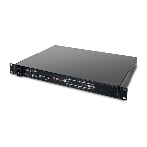
VIEWS Figure 6 shows in detail the front and rear views of the ATS. Fig. 6: front and rear views of ATS module. FIGURE 6 LEGEND: “INPUT A” switch SNMP expansion slot “INPUT B” switch Brakets for rack cabinet mounting Contacts port (see the relative paragraph for its Output 10A thermal breaker “OUTPUT 1”... -
Page 7: Control Panel
ONTROL PANEL The LED display on the front of the ATS shows the general functioning status of the ATS. Fig. 7: Focus of LED display. FIGURA 7 LEGEND: Preferred input indication Input “OK” indication Output supplied indication Alarm indication Preferred source selection button Acoustic signal mute button... -
Page 8: Installation
INSTALLATION NSTALLATION Figure 8 shows how to install the ATS module in a 19-inch bay (with a depth of 600mm), using the four screws supplied, at the desired height in the cabinet uprights. The module is not as wide as the bay and therefore does not obstruct the flow of air. Fig. -
Page 9: Communication Ports
The RS232 and USB communication ports allows remote monitoring of the ATS via software; available for free download at www.riello-ups.com. At the rear of the ATS a contact port is available that allows remote monitoring via internal relays (see related paragraph). -
Page 10: Contacts Port
ONTACTS PORT The contacts port is formed using eight (8) pins numbered from left to right (see fig. 9), which can be connected to an external monitoring system (such as a BMS) in order to monitor the operational status of the ATS. The external equipment must respects the voltage and current characteristics of contacts port. -
Page 11: Software
Connect the RS232 communication port of the ATS to a COM communication port of a PC via the serial cable provided*, or connect the USB port of the ATS to a USB port of the PC using a standard USB cable *. Download the software from www.riello-ups.com, selecting the desired operating system. Follow the installation program instructions. -
Page 12: Use
ISPLAY INDICATION The LED display shows the general functioning status of the ATS. The table below lists and describes the signal displayed. Fig. 11: Focus on LED display. FIGURE 11 LEGEND: Indication LED description LED status Condition Sound type SELECTED A Power A is preference SELECTED B Preference... -
Page 13: Troubleshooting Guide
TROUBLESHOOTING GUIDE Irregular operation of the ATS is not always an indication of a fault, and can often be resolved quickly and simply. Please consult the table below, which may help you deal with some commons issues. PROBLEM POSSIBLE CAUSE SOLUTION Connect the mains to the input plugs as indicated in the NO CONNECTION WITH... -
Page 14: Technical Data
TECHNICAL DATA Model Nominal Voltage 220/230/240 Vac Nominal Frequency 50 or 60Hz Maximum Current Switching time 8-12ms typical, 16ms maximum Display 7 LEDs display Buzzer Acoustic signal for overload, overtemperature, short-circuit or others internal faults. Protections Overload, overtemperature, short-circuit 483 (19”) x 330 x 44 (1U) mm Dimensions (W x D x H) Weight 5 Kg...
Need help?
Do you have a question about the MTA 16A and is the answer not in the manual?
Questions and answers