
Related Manuals for Ametek Land UNO U1 600/1600C-L


Summary of Contents for Ametek Land UNO U1 600/1600C-L
- Page 1 Fibroptic Thermometer User Guide Issue 7 30 April 2018 Publication Nº 198.013 Language: English © Land Instruments International, 2018...
- Page 2 IMPORTANT INFORMATION - PLEASE READ Health and Safety Information Read all of the instructions in this booklet - including all the WARNINGS and CAUTIONS - before using this product. If there is any instruction which you do not understand, DO NOT USE THE PRODUCT.
- Page 3 Web: www.ametek-land.com For further details on all AMETEK Land offices, distributors and representatives, please visit our website. Return of Damaged Goods IMPORTANT If any item has been damaged in transit, this should be reported to the carrier and to the supplier immediately.
- Page 4 Fibroptic Thermometer User Guide Blank...
-
Page 5: Table Of Contents
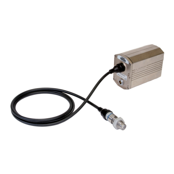
User Guide Fibroptic Thermometer Contents Introduction About this guide About the UNO Fibroptic thermometer Unpacking the thermometer Nomenclature Specifications U1 Series Thermometers U2 Series Thermometers V1 Series Thermometers Installing the UNO Fibroptic Thermometer Positioning the Optic Head Installing the lightguide Positioning the Thermometer Using the Thermometer Removing the chassis from the thermometer cover... - Page 6 Fibroptic Thermometer User Guide Fig. 1 Land Fibroptic UNO thermometer...
-
Page 7: Introduction
User Guide Fibroptic Thermometer Introduction 1.1 About this guide This guide gives the information necessary for you to operate a LAND UNO Fibroptic Thermometer. Basic information regarding installation is contained within the Installation Guide. 1.2 About the UNO Fibroptic thermometer The LAND UNO thermometer is an accurate, non contact thermometer designed for independent or STAND ALONE use. -
Page 8: Nomenclature
Fibroptic Thermometer User Guide 1.4 Nomenclature The thermometer detail label is on the rear face of the thermometer above the eyepiece. The thermometer instrument type nomenclature is explained in Fig. 3. Make a note of your thermometer’s instrument type and serial number in the space provided below. -
Page 9: Specifications
User Guide Fibroptic Thermometer Specifications 2.1 U1 Series Thermometers Thermometer Model U1 600/1600C-L U1 1100/2900F-L U1 800/2600C-L U1 1500/4700F-L Temperature Range: 600 to 1600°C 1100 to 2900°F 800 to 2600°C 1500 to 4700°F Wavelength: 1µm Averager Response: Adjustable 5ms to 5s (0 to 95%) Peak Picker: Adjustable 1.5 to 30%/s decay Emissivity:... -
Page 10: U2 Series Thermometers
Fibroptic Thermometer User Guide 2.2 U2 Series Thermometers Thermometer Model U2 300/1100C-L U2 600/2000F-L Temperature Range: 300 to 1100°C 600 to 2000°F Wavelength: 1.6µm Averager Response: Adjustable 5ms to 5s (0 to 95%) Peak Picker: Adjustable 1.5 to 30%/s decay Emissivity: Adjustable 0.10 to 1.00 Field of View (Nominal):... -
Page 11: V1 Series Thermometers
User Guide Fibroptic Thermometer 2.3 V1 Series Thermometers Thermometer Model V1 600/1600C-L V1 1100/2900F-L V1 1000/2600C-L V1 1800/4700F-L Temperature Range: 600 to 1600°C 1100 to 2900°F 1000 to 2600°C 1800 to 4700°F Wavelength: 0.85 to 1.1µm Averager Response: Adjustable 5ms to 5s (0 to 95%) Peak Picker: Adjustable 1.5 to 30%/s decay Non Greyness:... -
Page 12: Installing The Uno Fibroptic Thermometer
Fibroptic Thermometer User Guide Installing the UNO Fibroptic Thermometer 115/4.5 Mounting pad - 2 holes ¼" BSW 7/0.3 deep on 25/1.0 centres Recommended orientation of thermometer to prevent ingress of water, and build up of dirt etc. on electrical and lightguide connectors Minimum bend radius 50/2.0... -
Page 13: Positioning The Optic Head
User Guide Fibroptic Thermometer 3.1 Positioning the Optic Head If your UNO Fibroptic thermometer is fitted with a Laser Alignment Unit (e.g. U1 600/1600 C Y L), the laser be used to aid the installation of the thermometer optic head by defining the target area on which the optic head is aligned. This is particularly useful in applications where the target size is small and/or where correct alignment is critical. -
Page 14: Installing The Lightguide
Fibroptic Thermometer User Guide 3.2 Installing the lightguide When installing the fibre optic lightguide, observe the following precautions; Ensure that the lightguide is not be subjected to any tension or other undue force. It is not necessary to clamp or lash the lightguide to surrounding structures unless, by leaving it hanging, it will vibrate violently, be a nuisance or a hazard. -
Page 15: Using The Thermometer
User Guide Fibroptic Thermometer Using the Thermometer Before final installation of the thermometer, the internal controls (i.e. Emissivity, Averager response speed or Peak picker decay rate) must be set to match the particular measurement location. This involves removing the internal chassis from the thermometer cover. 4.1 Removing the chassis from the thermometer cover Caution Ensure that the thermometer is disconnected from the power supply before removing the chassis from the cover. -
Page 16: Location Of Controls
Fibroptic Thermometer User Guide 4.2 Location of controls The Emissivity/Non greyness and Peak Picker/Averager control switches are located on the left hand circuit board (When viewing the thermometer from the rear). See Fig. 6. Note The 4-way switch, SW1, is fitted in V series (i.e. ratio) thermometers only. 'O' ring Protection sleeve Control switches Gasket Fig. -
Page 17: Setting The Emissivity/Non Greyness Value
User Guide Fibroptic Thermometer 4.3 Setting the Emissivity/Non Greyness value 4.3.1 U series thermometers In U series (i.e. single wavelength) thermometers, the emissivity value is set using switches SW2 and SW3. Refer to Fig. 7. The emissivity can be set in the range 0.10 to 1.09 in steps of 0.01. When switch SW2 is set from 1 to 9, this denotes the first figure after the decimal point of the emissivity value. e.g. for an emissivity value of '0.83', set SW2 to '8' and SW3 to'3'. -
Page 18: Setting The Time Functions
Fibroptic Thermometer User Guide 4.3.2 V series thermometers In V series (i.e. ratio) thermometers, the non greyness value is set using switches SW1, SW2 and SW3. Refer to Fig. 8. The non greyness can be set in the range 0.800 to1.199 in steps of 0.001. The setting of switch SW1 denotes the first figure after the decimal point of the non greyness value. - Page 19 User Guide Fibroptic Thermometer 4.4.1 Averager The Averager time function is selected by setting switch, SW5, to position 1 (i.e. up). The Averager response time can be set, via switch SW4, to any one of the ten values shown in Fig. 9. A graphical explanation of the Averager time function is given in Fig.
-
Page 20: Note Your Settings
Fibroptic Thermometer User Guide 4.5 Note your settings This section is provided as a quick reference guide which enables you to look up the internal settings of your thermometer without having to remove it from the measurement location. Each time you adjust the settings, make a note of them in the spaces provided in Fig. -
Page 21: Electrical Connections
User Guide Fibroptic Thermometer 4.7 Electrical Connections NOTE Do not connect UNO thermometers to Land System 4 Signal Processors. The electrical connections for the thermometer power supply, Peak picker reset and temperature output are made via the 6-way socket on the rear of the thermometer. - Page 22 Fibroptic Thermometer User Guide 4.7.1 Cable connection schedule UNO thermometers can be connected, via the 6-way socket, to any compatible power supply and display equipment. A description of the required connections is given in the cable connection schedule, Fig. 15. Cable Colour Function Yellow...
- Page 23 User Guide Fibroptic Thermometer 4.7.2 Recommended wiring scheme It is recommended that the UNO thermometer is used in conjunction with the Land DIN Power supply Unit (DPU). In addition to providing the correct power supply voltage for the thermometer, the DPU has simple connections for mains supply, temperature output signal and Peak picker reset command signal.
- Page 24 Fibroptic Thermometer User Guide Notes on DPU interconnections (Fig. 16) ‘To indicator’ The indicator must have a ‘floating’ input i.e. a differen- tial or isolated input. ‘Reset control’ The reset control must be electrically isolated from the indicator. When used with an UNO, only the connections shown in Fig. 16 must be made to the DPU.
-
Page 25: Laser Alignment Unit
User Guide Fibroptic Thermometer Laser Alignment Unit 5.1 About the Laser Alignment Unit The Laser Alignment Unit for Land UNO Fibroptic Thermometers is designed to aid the installation of the thermometer optic head by defining the target area on which the optic head is aligned. This is particularly useful in applications where the target size is small and/or where correct alignment is critical. The Laser Alignment Unit may also be used for finding the correct distance from the target at which to mount the optic head, as the laser image is sharpest at this point. - Page 26 Fibroptic Thermometer User Guide MADE IN ENGLAN D TYPE: U1 1100/2900F L 10 A10 SERIAL No. 0000000/00/00 CLASS 1 LASER PRODUCT Fig. 18 Location of warning label on thermometer fitted with Laser Alignment Unit UN970331 Laser Alignment Unit activating switch Fig. 19 Location of the Laser Alignment Unit activating switch and LED UN970332 Page 20...
-
Page 27: Using The Laser Alignment Unit
User Guide Fibroptic Thermometer 5.3 Using the Laser Alignment Unit Warning Class 1 Laser Product. This laser product does not permit human access to laser radiation in excess of the accessible emission limits of Class 1 for applicable wavelengths and emission durations. -
Page 28: Target Size Tables
Fibroptic Thermometer User Guide Target Size Tables To find out which table applies to your thermometer: Refer to the detail label, above the lightguide connector on the thermometer, to find the type of optic head (i.e. A10, A25 or A50) fitted to your thermometer. Refer to the specification table for your thermometer, Section 1.5, to find the field of view (i.e. 25:1 or 75:1) for the optic head. 6.1 Optic Head A10, Field of View 25:1 (Red spacer) Target diameter 15.0mm 12.3mm 9.5mm 6.8mm 4.0mm 8.8mm... -
Page 29: Optic Head A25, Field Of View 25:1 (Blue Spacer)
User Guide Fibroptic Thermometer 6.3 Optic Head A25, Field of View 25:1 (Blue spacer) Target diameter 11.2mm 11.0mm 10.7mm 10.5mm 10.2mm 10.0mm 14.2mm 0.44in 0.43in 0.42in 0.41in 0.40in 0.39in 0.56in 50mm 100mm 150mm 200mm 250mm 300mm 1.97in 3.94in 5.91in 7.87in 9.84in 11.81in Target distance... -
Page 30: Optic Head A50, Field Of View 25:1 (No Spacer)
Fibroptic Thermometer User Guide 6.5 Optic Head A50, Field of View 25:1 (No spacer) Target diameter 10.3mm 12.8mm 15.4mm 17.9mm 20.5mm 23.0mm 26.1mm 0.41in 0.50in 0.61in 0.70in 0.81in 0.91in 1.03in 100mm 200mm 300mm 400mm 500mm 600mm 3.94in 7.87in 11.81in 15.75in 19.69in 23.62in Target distance... -
Page 31: Emissivity Tables
User Guide Fibroptic Thermometer Emissivity tables In order to obtain accurate temperature measurements, the emissivity value of the target surface must be known. This section of the Thermometer User Guide contains emissivity values of the most commonly measured materials for each UNO thermometer. Where no emissivity value is quoted, this means that either the thermometer is not suitable for the measurement application or the temperature of the target is outside the thermometer’s measurement span. -
Page 32: Metals
Fibroptic Thermometer User Guide 7.3 Metals Metals Material Thermometer Series Aluminium 0.13 0.09 0.08 oxidised 0.40 0.40 0.40 Chromium 0.43 0.34 oxidised 0.75 0.80 Cobalt 0.32 0.28 oxidised 0.70 0.65 Copper 0.06 0.05 0.04 oxidised 0.85 0.85 0.85 Gold 0.05 0.02 0.02 Iron &... -
Page 33: Miscellaneous
User Guide Fibroptic Thermometer 7.4 Miscellaneous Miscellaneous Materials Material Thermometer Series Asbestos (board/paper/cloth) 0.90 0.90 Asphalt 0.85 0.85 graphite 0.85 0.85 Carbon soot 0.95 0.95 Cement & Concrete 0.65 0.70 Cloth - all types, close weave (Open weave reduces 0.75 0.80 0.85 emissivity) -
Page 34: Maintenance
Fibroptic Thermometer User Guide Maintenance 8.1 Optic head After initial installation, make regular inspections of the lens in order to establish a cleaning cycle. If the lens requires cleaning, it is preferable to do so without disconnecting the lightguide from the optic head. Clean the lens with a soft cloth and a little alcohol if necessary. - Page 35 PRODUCT WARRANTY Thank you for purchasing your new product from Land Instruments International. This Land manufacturer’s ‘back-to-base’ warranty covers product malfunctions arising from defects in design or manufacture. The warranty period commences on the instrument despatch date from the Land Instruments International Ltd.
- Page 36 PRODUCT WARRANTY EXCLUSIONS FROM WARRANTY It should be noted that costs associated with calibration checks which may be requested during the warranty period are not covered within the warranty. Land reserve the right to charge for service/calibration checks undertaken during the warranty period if the cause is deemed to fall outside the terms of the warranty.
Need help?
Do you have a question about the UNO U1 600/1600C-L and is the answer not in the manual?
Questions and answers