
Related Manuals for Ametek Land UNO Series


Summary of Contents for Ametek Land UNO Series
- Page 1 Thermometer User Guide Issue 12 14 March 2019 Publication Nº 198.012 Language: English © AMETEK Land Instruments International, 2019...
- Page 2 Observe precautions for handling electrostatic discharge sensitive devices. Equipment Operation Use of this instrument in a manner not specified by AMETEK Land may be hazardous. Read and understand the user documentation supplied before installing and operating the equipment. The safety of any system incorporating this equipment is the responsibility of the assembler.
- Page 3 This manual is provided as an aid to owners of AMETEK Land’s products and contains information proprietary to AMETEK Land. This manual may not, in whole or part, be copied, or reproduced without the expressed written consent of AMETEK Land.
- Page 4 Thermometer User Guide...
-
Page 5: Table Of Contents
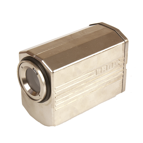
User Guide Thermometer Contents Introduction About this guide About the thermometer About UNO Unpacking the thermometer Nomenclature Specifications U1 Series Thermometers U2 Series Thermometers U4 Series Thermometers U5 Series Thermometers U6 Series Thermometers U8 Series Thermometers V1 Series Thermometers Installing the Thermometer Choosing a location for the thermometer Using the Thermometer Removing the chassis from the thermometer cover... - Page 6 Thermometer User Guide Fig. 1 Land UNO thermometer S4970222 Air Purge Thermometer Jacket Back Cap Fig. 2 Thermometer with Air Purge, Protection Jacket and Back Cap S4970223...
-
Page 7: Introduction
User Guide Thermometer Introduction 1.1 About this guide This guide gives the information necessary for you to operate a LAND UNO thermometer. Basic information regarding installation is contained within the Installation Guide. 1.2 About the thermometer The LAND UNO thermometer is a highly accurate, focusable, non contact thermometer designed for independent or STAND ALONE use. -
Page 8: Nomenclature
Thermometer User Guide 1.5 Nomenclature The thermometer detail label is on the rear face of the thermometer above the eyepiece. The thermometer instrument type nomenclature is explained in Fig. 3. Make a note of your thermometer’s instrument type and serial number in the space provided below. -
Page 9: Specifications
User Guide Thermometer Specifications 2.1 U1 Series Thermometers Thermometer Model U1 600/1600C U1 1100/2900F U1 800/2600C U1 1500/4700F Temperature Range: 600 to 1600°C 1100 to 2900°F 800 to 2600°C 1500 to 4700°F Wavelength: 1µm Averager Response: Adjustable 5ms to 5s (0 to 95%) Peak Picker: 1.5 to 30%/s decay Emissivity:... -
Page 10: U2 Series Thermometers
Thermometer User Guide 2.2 U2 Series Thermometers Thermometer Model U2 300/1100C U2 600/2000F Temperature Range: 300 to 1100°C 600 to 2000°F Wavelength: 1.6µm Averager Response: Adjustable 5ms to 5s (0 to 95%) Peak Picker: 1.5 to 30% /s decay Emissivity: 0.10 to 1.00 Sighting: 6°... -
Page 11: U4 Series Thermometers
User Guide Thermometer 2.3 U4 Series Thermometers Thermometer Model U4 50/250C U4 150/500F U4 150/550C U4 300/1000F Temperature Range: 50 to 250°C 150 to 500°F 150 to 550°C 300 to 1000°F Wavelength: 2.4µm Averager Response: Adjustable 5ms to 5s (0 to 95%) Peak Picker: 1.5 to 30% /s decay Emissivity:... -
Page 12: U5 Series Thermometers
Thermometer User Guide 2.4 U5 Series Thermometers Thermometer Model U5 400/1300C U5 750/2400F U5 1000/2500C U5 1800/4500F Temperature Range: 400 to 1300°C 750 to 2400°F 1000 to 2500°C 1800 to 4500°F Wavelength: 4.8 to 5.2µm Averager Response: 100ms to 5s (to 95%) Peak Picker: 1.5 to 30%/s decay Emissivity:... -
Page 13: U6 Series Thermometers
User Guide Thermometer 2.5 U6 Series Thermometers Thermometer Model U6 0/300C-V U6 100/700C-V Temperature Range: 0 to 300°C 100 to 700°C Wavelength: 3 to 5µm Averager Response: Adjustable 100ms to 5s (0 to 95%) Peak Picker: 1.5 to 30% /s decay Emissivity: 0.10 to 1.00 Sighting:... -
Page 14: U8 Series Thermometers
Thermometer User Guide 2.6 U8 Series Thermometers Thermometer Model U8 0/1000C-V Temperature Range: 0 to 1000°C Wavelength: 8 to 14µm Averager Response: Adjustable 100ms to 5s (0 to 95%) Peak Picker: 1.5 to 30% /s decay Emissivity: 0.10 to 1.00 Sighting: 6°... -
Page 15: V1 Series Thermometers
User Guide Thermometer 2.7 V1 Series Thermometers Thermometer Model V1 600/1600C V1 1100/2900F V1 1000/2600C V1 1800/4700F Temperature Range: 600 to 1600°C 1100 to 2900°F 1000 to 2600°C 1800 to 4700°F Wavelength: 0.85 to 1.1µm Averager Response: Adjustable 15ms to 5s (0 to 95%) Peak Picker: 1.5 to 30%/s decay Non Greyness:... -
Page 16: Installing The Thermometer
Thermometer User Guide Installing the Thermometer This section contains similar information to the thermometer Installation Guide. If the thermometer is to be used in conjunction with a protection jacket and air purge, refer to the installation guides provided with those accessories. If the thermometer is to be installed in a location where the ambient temperature is within the ranges specified for the thermometer, and no air purging is required to keep the lens clean, the thermometer can be mounted... - Page 17 User Guide Thermometer 80mm/3.2in Allow 480mm/19.0in. for sighting access Mounting Pad: 2 holes, ¼in BSW, 7mm/0.3in deep on 25mm/0.98in centres Fig. 4 Thermometer installation dimensions S4970225 Ensure that the thermometer has an unobstructed view of the target Target Size ( d ) Target Distance ( s ) Target Size ( d ) = Target Distance ( s ) FOV*...
-
Page 18: Using The Thermometer
Thermometer User Guide Using the Thermometer Before final installation of the thermometer, the internal controls (i.e. Emis- sivity, Averager response speed or Peak picker decay rate) must be set to match the particular measurement location. This involves removing the internal chassis from the thermometer cover. 4.1 Removing the chassis from the thermometer cover Caution Ensure that the thermometer is disconnected from the power supply... -
Page 19: Location Of Controls
User Guide Thermometer 4.2 Location of controls The Emissivity/Non greyness and Peak Picker/Averager control switches are located on the left hand circuit board (When viewing the thermometer from the rear). See Fig. 7. Note The 4-way switch, SW1, is fitted in V series (i.e. ratio) thermometers only. -
Page 20: Setting The Emissivity/Non Greyness Value
Thermometer User Guide 4.3 Setting the Emissivity/Non Greyness value 4.3.1 U series thermometers In U series (i.e. single wavelength) thermometers, the emissivity value is set using switches SW2 and SW3. Refer to Fig. 8. The emissivity can be set in the range 0.10 to 1.09 in steps of 0.01. When switch SW2 is set from 1 to 9, this denotes the first figure after the decimal point of the emissivity value. -
Page 21: Setting The Time Functions
User Guide Thermometer Switches Greyness 0.800 SW2 SW3 0.995 1.008 1.100 SW4 SW5 1.199 Fig. 9 Non greyness setting for ‘V’ series thermometers 4.4 Setting the Time Functions The UNO thermometer is fitted with both Averager and Peak Picker time functions. - Page 22 Thermometer User Guide Note Setting the Averager response speed to a value faster than that quoted in the specification for your thermometer will not produce an increase in response speed beyond the specified value. e.g. Fastest possible re- sponse speed for a V1 UNO is 15ms. Raw signal Fast averager Slow averager...
-
Page 23: Note Your Settings
User Guide Thermometer 4.5 Note your settings This section is provided as a quick reference guide which enables you to look up the internal settings of your thermometer without having to remove it from the measurement location. Each time you adjust the settings, make a note in the spaces provided in Fig. 13. Serial Number Date Settings... -
Page 24: Refitting The Chassis Into The Thermometer Cover
Thermometer User Guide 4.6 Refitting the chassis into the thermometer cover When all internal controls have been set to suit your requirements, refit the thermometer chassis into the cover. Ensure that the gasket is fitted correctly on the inner face of the ther- mometer rear panel. - Page 25 User Guide Thermometer If the required target is not within the graticule, adjust the thermometer mounting until the target fills the graticule. NOTE A range of thermometer mounting accessories, to suit all measurement locations, is available from Land Instruments International. Turn the focus ring to bring the target into focus.
-
Page 26: Electrical Connections
Thermometer User Guide 4.8 Electrical Connections NOTE Do not connect UNO thermometers to Land System 4 Signal Processors. The electrical connections for the thermometer power supply, Peak picker reset and temperature output are made via the 6-way socket on the rear of the thermometer. - Page 27 User Guide Thermometer 4.8.1 Cable connection schedule UNO thermometers can be connected, via the 6-way socket, to any compatible power supply and display equipment. A description of the required connections is given in the cable connection schedule, Fig. 17. Cable Colour Function Yellow 4 to 20mA linear temperature signal drive...
- Page 28 Thermometer User Guide 4.8.2 Recommended wiring scheme It is recommended that the UNO thermometer is used in conjunction with the Land DIN Power supply Unit (DPU). In addition to providing the correct power supply voltage for the thermometer, the DPU has simple connections for mains supply, temperature output signal and Peak Picker reset command signal.
- Page 29 User Guide Thermometer Notes on DPU interconnections (Fig. 18) ‘To indicator’ The indicator must have a ‘floating’ input i.e. a differential or isolated input. ‘Reset control’ The reset control must be electrically isolated from the indicator. When used with an UNO, only the connections shown in Fig. 18 must be made to the DPU.
-
Page 30: Emissivity Tables
Thermometer User Guide Emissivity tables In order to obtain accurate temperature measurements, the emissivity value of the target surface must be known. This section of the Thermometer User Guide contains emissivity values of the most commonly measured materials for each UNO thermometer. Where no emissivity value is quoted, this means that either the thermometer is not suitable for the measurement applica- tion or the temperature of the target is outside the thermometer’s measure- ment span. -
Page 31: Metals
User Guide Thermometer 5.3 Metals Metals Material Thermometer Series Aluminium 0.13 0.09 0.08 0.05 0.03 oxidised 0.40 0.40 0.40 0.30 0.35 Chromium 0.43 0.34 0.15 0.07 oxidised 0.75 0.80 0.85 Cobalt 0.32 0.28 0.18 0.04 oxidised 0.70 0.65 0.35 Copper 0.06 0.05 0.04... -
Page 32: Miscellaneous
Thermometer User Guide 5.4 Miscellaneous Miscellaneous Materials Material Thermometer Series Asbestos (board/paper/cloth) 0.90 0.90 0.90 0.90 Asphalt 0.85 0.85 0.90 0.85 graphite 0.85 0.85 0.85 0.80 Carbon soot 0.95 0.95 0.95 0.95 Cement & Concrete 0.65 0.70 0.90 0.90 Cloth - all types, close weave (Open weave reduces 0.75 0.80... -
Page 33: Maintenance
User Guide Thermometer Maintenance Thermometer maintenance consists mainly of ensuring that the lens is clean. If the lens becomes dirty clean it with lens cleaning fluid and a soft cloth. If it is found that the lens is repeatedly becoming dirty, it may be necessary to use the thermometer in conjunction with the System 4 air purge (LAND Part Nº... - Page 34 Thermometer User Guide Page 28...
Need help?
Do you have a question about the UNO Series and is the answer not in the manual?
Questions and answers