
Related Manuals for Ametek Land CDA


Summary of Contents for Ametek Land CDA
- Page 1 Incinerator Thermometer User Guide Issue 5 04 January 2017 Publication Nº 800682 Language: English Copyright © 2002 - 2017 Land Instruments International...
- Page 2 IMPORTANT INFORMATION - PLEASE READ Health and Safety Information Read all of the instructions in this booklet - including all the WARNINGS and CAUTIONS - before using this product. If there is any instruction which you do not understand, DO NOT USE THE PRODUCT.
- Page 3 Web: www.landinst.com For further details on all AMETEK Land offices, distributors and representatives, please visit our websites. Return of Damaged Goods IMPORTANT If any item has been damaged in transit, this should be reported to the carrier and to the supplier immediately.
- Page 4 Thermometer User Guide...
-
Page 5: Table Of Contents
User Guide Thermometer Contents Introduction General Introduction About the CDA Incinerator Thermometer Application Specifications Installing the Thermometer Introduction Aiming Consideration Using the Thermometer Location of Controls Adjusting the ‘Emissivity’ Value Adjusting the Averager ‘Response Time’ Noting ‘Emissivity’ and ‘Response Time’ Settings... - Page 6 Thermometer User Guide...
-
Page 7: Introduction
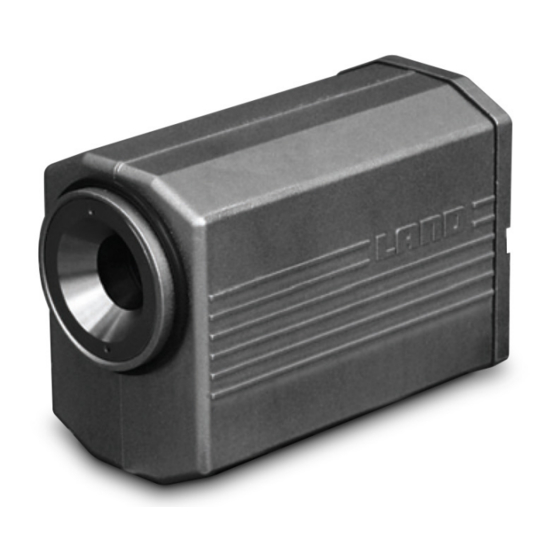
1.2 About the CDA Incinerator Thermometer The LAND CDA Incinerator Thermometer is a highly accurate, non contact thermometer designed for independent or “STAND ALONE” use. Thermometer features include: •... -
Page 8: Application
In a typical incinerator application, the CDA is mounted externally onto the incinerator wall, positioned approximately 2 metres above the bed. It is fixed to a protective flanged sight tube which penetrates through the incinerator wall. - Page 9 User Guide Thermometer 600mm/23.6in Parallel FOV 20mm/0.79in Diverging FOV Lens Fig. 3 - Thermometer Sighting diagram 294003 3x equi-spaced mounting Thermometer removal clearance holes 6.5 to 7.0/0.26 to 0.28 Approx. 200/8.0 clearance for M6 bolts Side View 150/5.9 170/6.7 110/4.4 Top View 430/17.0 All dimensions in mm/in...
-
Page 10: Specifications
Thermometer User Guide Specifications Temperature Range 400 to 1800°C/752 to 3272°F Output: 4 to 20mA linear (2-wire loop connection) Must not be isolated to >50V from earth 20mm/0.79in parallel Field of View: to 600mm/23.6in (nominal) Permissible misalignment between thermometer Alignment: optical and mechanical axes = 1°... -
Page 11: Installing The Thermometer
Installing the Thermometer 3.1 Introduction The information detailed within this section of the CDA User Guide, should be cross-referred with information found in the CDA Installation Guide. If the thermometer is to be used in conjunction with a protection jacket and air purge (recommended), refer to the Installation Guides supplied with the relevant accessory. - Page 12 Thermometer User Guide 100 200 500 600 Sight tube length (mm) Fig. 6 - Minimum recommended Sight Tube diameters 294006 Thermometer error versus path length for several CO concentrations. Gas temperature 1500K -100 8% CO -150 6% CO 4% CO 2% CO -200 Path length (metres)
- Page 13 User Guide Thermometer Thermometer error versus path length for several CO concentrations. Gas temperature 1200K -100 8% CO -150 6% CO 4% CO 2% CO -200 Path length (metres) Fig. 8 - Thermometer error at 1200K gas temperature 294008 Page 7...
-
Page 14: Using The Thermometer
Thermometer User Guide Using the Thermometer It is recommended that the ‘Emissivity’ and ‘Response Time’ controls are set to match the requirements of the particular measurement location before installation. This is particularly relevant if the thermometer is to be used in a location which is difficult to access and/or used in conjunction with a jacket and back cap. -
Page 15: Adjusting The Emissivity Value
The emissivity can be set in the range 0.10 to 1.00 in steps of 0.01. The CDA is supplied with the emissivity factory-set to 1.00. The Emissivity value is set using switches SW1 and SW2. See Fig. 10. -
Page 16: Adjusting The Averager Response Time
For longer time constants (e.g. to mimic thermocouples), an averaging meter is advised. Suitable units provide 0 to 999 seconds of response, 4 to 20 mA retransmission output and also power to the CDA. For further information, contact Land Instruments International. -
Page 17: Noting 'Emissivity' And 'Response Time' Settings
User Guide Thermometer 4.4 Noting ‘Emissivity’ and ‘Response Time’ Settings It is advisable to make a note of the settings for ‘Emissivity’ and ‘Response Time’, once these settings have been determined and verified. Each time a re-adjustment is made to the settings, make a note in the table below, using the spaces provided. -
Page 18: Electrical Connections
Thermometer User Guide Electrical Connections 5.1 Thermometer Operation The LAND Incinerator Thermometer is a rugged, stand alone, non contact thermometer, designed for measuring relatively low temperatures in hostile environments. It has a temperature measurement range of 400 to 1800°C/752 to 3272°F. The thermometer operates on a simple 4 to 20mA current loop. -
Page 19: Electrical Connections
V+, 4 to 20mA V-, 4 to 20mA Black Electrical connections to the CDA thermometer must be made through the prewired plug supplied with the thermometer or through the plug housed in the protective jacket back cap. To connect either plug type to the thermometer socket: •... -
Page 20: Loop Resistance
Thermometer User Guide 5.3 Loop Resistance The maximum allowable resistance in the thermometer current loop for a givenpower supply voltage is illustrated in Fig. 13. Information on how to adjust thepower supply voltage for a LAND power supply is given in the Power Supply Unit User Guide. -
Page 21: Mounting And Accessories
User Guide Thermometer Mounting and Accessories 6.1 Recommendations The CDA thermometer is compatible with all Land System 4 thermometer mountings and accessories. For the majority if incinerator and furnace applications, the following package of accessories is recommended (see Fig. 2): Air Purge: Land Part No. -
Page 22: Maintenance
(water and air supplies) are set correctly and are routinely checked. For further information detailing services supplied to any CDA thermometer system mountings and accessories, cross- refer to the System 4 Thermometer Mountings and Accessories Installation Guide. - Page 23 PRODUCT WARRANTY Thank you for purchasing your new product from Land Instruments International. This Land manufacturer’s ‘back-to-base’ warranty covers product malfunctions arising from defects in design or manufacture. The warranty period commences on the instrument despatch date from the Land Instruments International Ltd.
- Page 24 PRODUCT WARRANTY EXCLUSIONS FROM WARRANTY It should be noted that costs associated with calibration checks which may be requested during the warranty period are not covered within the warranty. Land reserve the right to charge for service/calibration checks undertaken during the warranty period if the cause is deemed to fall outside the terms of the warranty.
Need help?
Do you have a question about the CDA and is the answer not in the manual?
Questions and answers