
Related Manuals for Grundfos FireSAFE Series


Summary of Contents for Grundfos FireSAFE Series
- Page 1 FireSAFE Residential Range Installation and Operating instructions For use in Residential properties...
- Page 2 Construction Products Regulation EU no. 305/2011 Standard used: EN 12845:2004+A2:2009 This EC/EU declaration of conformity is only valid when published as part of the Grundfos Installation and Operating instructions (publication number 98952970). Authorised signature: John Austin – Engineering Manager...
-
Page 3: Table Of Contents
8.1 Delivery and Handling 8.2 Delivery Inspection upon receipt 8.3 Warranty 8.4 Site Storage 8.5 Frost Protection 8.6 Operating Environment 8.7 Installation Location 8.8 Breaktanks and Mains water connection 8.9 Installation General requirements 8.10 Operating Conditions www.grundfos.co.uk Page 3 of 40... - Page 4 For quick reference the front page of this Installation and Operating manual should be filled in with the contact details of the Installer or building supervisor. This manual should stay with the FireSAFE unit. www.grundfos.co.uk Page 4 of 40...
-
Page 5: Symbols Used In This Document
For CR Pump specific information please consult the CR Installation and Operating manual supplied with the product documentation. All of the above documents can also be found on the Grundfos Product Center website at: www.grundfos.co.uk 4.0 Product Identification The FireSAFE unit has a silver label attached to the top of the front cover. -
Page 6: Product Introduction, Description And Application
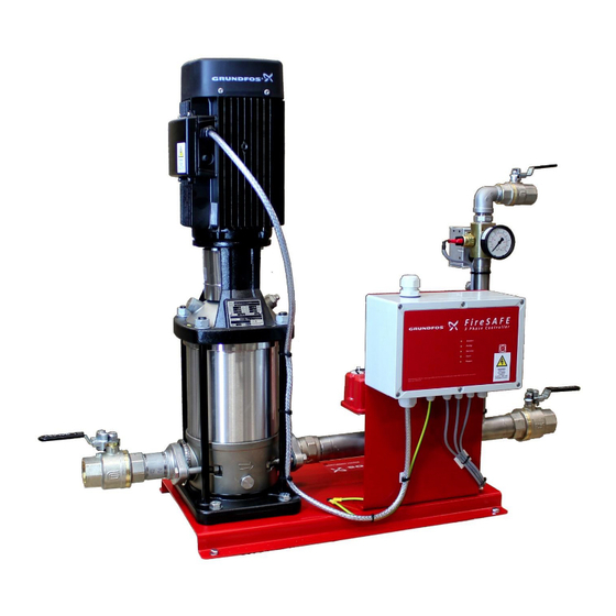
5.0 Product Introduction, Description and Application The Grundfos FireSAFE (Safe Active Fire Equipment) range of pump packages is designed to comply with the recommendations of British Standard, BS9251:2014. (BS9251:2014 Fire sprinkler systems for domestic and residential occupancies. Code of practice) The product is designed to the highest standards and is intended to give many years of trouble free service while protecting lives and property. -
Page 7: Key Product Components
Only sprinkler heads affected directly by the heat source will operate. This loss of pressure is detected by the Grundfos FireSAFE unit, via an internal pressure switch, activating the pump. 6.0 Key Product Components 6.1 Pump... -
Page 8: Controller
6.7 Controller The Controller has been specifically designed by Grundfos to conform with BS 9251:2014, integrate key system signals, monitor condition and to operate automatically. The following are features of the FireSAFE controller: Modes of operation: o Pressure maintenance... - Page 9 Pressing and holding the test button for >10 seconds will start the pump condition learning and return to the normal operation. This will also reset all Faults and Service requests and return to the normal operation. (Press and hold the test button until a long beep is heard). www.grundfos.co.uk Page 9 of 40...
-
Page 10: Integration Of Digital Signals
7.2 Integration of digital signals (Low water level switch and Fire alarm device) The FireSAFE unit has been specifically designed with the ability to power and relay digital signals. The signals could be from any source but Grundfos suggest the following important signals are used: Digital input/output (DI2/D02) –Tank low water level switch device, to give a warning once... -
Page 11: Automatic Pump Health Test
The Pump health can be manually tested by pressing the Test/Reset button until the pump runs. The test is the same as the Automatic weekly pump self-test. Press and hold the Test Pump runs button for >2 seconds www.grundfos.co.uk Page 11 of 40... -
Page 12: Excessive Pump Operation
The Fault Digital output and Fault LED are activated. This can be reset after it has been attended to by following the service mode instructions in section 7.1. This should be done against a closed valve system pressurised condition. www.grundfos.co.uk Page 12 of 40... -
Page 13: General Information
8.3 Warranty The Grundfos warranty covers all defects within the FireSAFE originating from faulty workmanship and/or materials for a period of two years from the date of installation or thirty months from the date of despatch from the factory, whichever is the shorter. -
Page 14: Frost Protection
Grundfos do not accept any responsibility for the use of FireSAFE unit to pump liquids which could be construed as being hazardous to health either by touch, ingestion or inhalation of fumes or gases given off by the liquid. -
Page 15: Breaktanks And Mains Water Connection
FireSAFE unit, it must however have a type AB Air Gap, supplied and installed in accordance with the Water Byelaws Regulations. Grundfos can offer a suitable break tank. Check that the water storage tank has adequate capacity to meet/exceed the demand. -
Page 16: Operating Conditions
Do not attempt to supply electricity to the electric motor or re-pressure the pipe work system without first ensuring that all protective coverings are held securely in their correct positions. www.grundfos.co.uk Page 16 of 40... -
Page 17: Pressure Switch Setting
The FireSAFE unit requires fitting with a suitable flame retardant power cable. The power cable must be wired into a suitable lockable isolator switch to provide the power to the system and to the Mains In terminals in the below PCB layout. www.grundfos.co.uk Page 17 of 40... - Page 18 The ‘pump’ connections will be wired in from the factory. On insulation the ‘mains input’ connections need to be wired as shown to the left. Figure 10 Three Phase mains power cabling instructions www.grundfos.co.uk Page 18 of 40...
-
Page 19: Digital Input And Output Connections
1 x cable gland is provided in the Controller box for a multi-core cable to carry digital out signals. (OUT1, OUT2, OUT3) The PCB terminals shown above will accept conductors up to 1 mm in cross section diameter. It is recommended that the conductors are ferruled first. www.grundfos.co.uk Page 19 of 40... - Page 20 The Digital inputs/outputs are each designed as per below. Figure 10 – Configuration of digital input and output connectors Earth (typically unused) Normally Common Normally Open 24 V DC for Inputs Closed VFC for outputs www.grundfos.co.uk Page 20 of 40...
- Page 21 3. See the correct direction of rotation of the pump on the 7. Close the vent valve when a steady stream of liquid runs motor fan cover. out of it. Completely open the discharge isolating valve. 4. Start the pump and check the direction of rotation. www.grundfos.co.uk Page 21 of 40...
- Page 22 Page 22 of 40...
-
Page 23: Installation Checklist
Review all of the above actions, if the commissioning phase does not follow immediately after, replace the front cover and screws. Leave the unit in a safe condition System is ready to Commission www.grundfos.co.uk Page 23 of 40... -
Page 24: Commissioning Checklist
Weekly Test time set at this time. Clean up area and ensure safe for user, Mains isolator is locked in the ON position. Update History log at back of this System is ready to Verify manual www.grundfos.co.uk Page 24 of 40... -
Page 25: System Verification Test Checklist
Inform customer and any Clean up area and ensure safe for user. monitoring services that the system Mains isolator is locked in the ON position. is operational. Handover this Isolating valves locked in the OPEN position. manual. www.grundfos.co.uk Page 25 of 40... -
Page 26: Operation
Check that the pump operates quietly and smoothly by This will reset the weekly test time. pressing and holding the test button until the pump starts. The weekly test time may need resetting after this. www.grundfos.co.uk Page 26 of 40... -
Page 27: User Maintenance
Should any faults be found check the symptoms with the Fault Finding Checklist first, and if necessary contact Grundfos Pumps Ltd for advice or Grundfos Service for Maintenance and Service. Details can be found on the front of this manual and also the History log section 12.0 User Maintenance... - Page 28 Close test line isolating valve been achieved in test line Perform annual system test. per BS 9251 requirements Check unit responds to pressure drop, and enters: See section 6 System Pressure Maintenance Mode www.grundfos.co.uk Page 28 of 40...
- Page 29 Weekly Test time set at this time. Clean up area and ensure safe for user Update History log at back of this manual. Inform customer that the System is ready to Operate system is Operational. Handover this manual. www.grundfos.co.uk Page 29 of 40...
-
Page 30: Technical Information
FIRESAFE CRI15-4 3PH FSV15053 FIRESAFE CRI15-5 3PH FSV15063 FIRESAFE CRI15-6 3PH FSV15073 FIRESAFE CRI15-7 3PH FSV15083 FIRESAFE CRI15-8 3PH 11.3 98388267 FIRESAFE CRI15-9 3PH 9.93 12.7 FSV15103 FIRESAFE CRI15-10 3PH 11.2 13.9 FSV20073 FIRESAFE CRI20-7 3PH 10.1 www.grundfos.co.uk Page 30 of 40... - Page 31 FIRESAFE CR15-4 3PH 98938600 FIRESAFE CR15-5 3PH 98938662 FIRESAFE CR15-6 3PH 98938664 FIRESAFE CR15-7 3PH 98938681 FIRESAFE CR15-8 3PH 11.3 98938683 FIRESAFE CR15-9 3PH 9.93 12.7 98938567 FIRESAFE CR15-10 3PH 11.2 13.9 98938701 FIRESAFE CR20-7 3PH 10.1 www.grundfos.co.uk Page 31 of 40...
-
Page 32: Commissioning, Dismantling And Disposal
Remove the two bolts holding the front cover in place Lift off the front cover and disconnect the earth bonding wire to the front cover and place the cover in safe place out of the way www.grundfos.co.uk Page 32 of 40... -
Page 33: Disposal
In case such waste collection services do not exist or cannot handle the materials used in the product, please deliver the product or any hazardous materials from it to your nearest Grundfos company or service workshop. Local and National environmental legislation must always be complied with. www.grundfos.co.uk... -
Page 34: Fault Finding Checklists
Refer to Service mode section 7.1 to reset Alarm! LED ON Flow switch activated, Sprinkler head activated. Internal buzzer sounding constantly Restore system pressure and press Test/Reset Digital output D03 changed over button on controller www.grundfos.co.uk Page 34 of 40... - Page 35 C) Check electrical supply to pump 4) Faulty Controller. D) Contact your system 5) Power wiring to pump. supplier/Grundfos Service for remedial action. Pump does not reach the 1) Not enough water getting to a) Check suction isolating valve is duty point but continues the pump.
-
Page 36: History Log
Y / N Flow switch input used = Y / N Connected to Alarm Panel = Y / N Connected to Siren/Buzzer = Y / N Connected to monitoring Service = Y / N Other www.grundfos.co.uk Page 36 of 40... - Page 37 Page 37 of 40...
- Page 38 Page 38 of 40...
- Page 39 Page 39 of 40...
- Page 40 Part no: 98635621 – Installation and Operating Manual – FireSAFE ECM: 1188727 dd 07/07/2016 It is the continuing policy of Grundfos to develop and improve our products, and we reserve the right to amend prices and specification without prior notice.
Need help?
Do you have a question about the FireSAFE Series and is the answer not in the manual?
Questions and answers