Table of Contents
Advertisement
Advertisement
Table of Contents

Related Manuals for 4D systems gen4-FTDI Series


Summary of Contents for 4D systems gen4-FTDI Series
- Page 1 gen4-FTDI Display Series - GETTING STARTED MANUAL...
-
Page 2: Table Of Contents
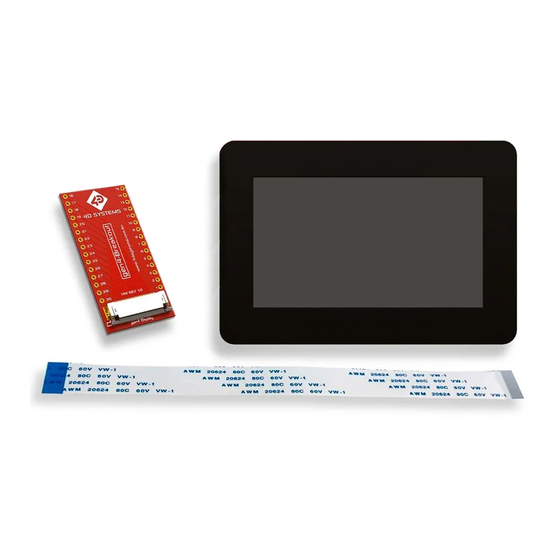
• Hardware • Software WHAT’S IN THE BOX Gen4-FT812-43CT- gen4-Breakout 15-way to 30-way Flat Flex Cable (FFC) Supporting documents, datasheet, CAD step models and application notes are available on the 4D Systems website. gen4-FTDI Display Series - GETTING STARTED MANUAL... -
Page 3: Introduction
• Reference Documents The gen4-FT81X-XXT/CT-CLB is part of embedded SPI display manufactured by 4D Systems. The module features a 4.3”, 5.0”, or 7.0” colour TFT LCD display, with resistive or capacitive touch. It is powered by the FT812/FT813 Video Engine, which targets high quality graphics displays with Widget support, designed to offload the Host Processor and provide a variety of graphics features. -
Page 4: System Requirements
It is entirely up to the user to select their host controller and use it to drive the display. Note: The host controller is a device such as an Arduino or a Raspberry Pi. These devices are not supplied by 4D Systems. gen4-FTDI Display Series - GETTING STARTED MANUAL... -
Page 5: Connecting The Display Module To The Host
CONNECTING THE DISPLAY MODULE TO THE HOST This section shows the complete instructions for connecting the display to the host controller. Hardware Software Any Software which FFC Cable gen4-Breakout Display Module Host Controller can drive your host controller Adaptor Adaptor Cable (FFC) Connection Options... -
Page 6: Getting Started With A Simple Project
GETTING STARTED WITH A SIMPLE PROJECT After successfully connecting the display module to the host controller you are using, you can now start creating a basic application. This section shows how to show a simple keyboard on the display module using the example uploaded on the FTDI chip website. - Page 7 (c.) Edit the line 148 of the Platform.h and add the configuration for the display &&!defined(GEN4FT812_43) The completed code should be like this: #if (!defined(VM800P43_50) && !defined(VM800P35) &&!defined(VM801P43_50) &&!defined(VM800B43_50) &&!defined(VM800B35) &&!defined(VM801B43_50) &&!defined(GEN4FT812_43) ) 4. Save the following changes on the file and upload the program on the Arduino using the Arduino IDE.
-
Page 8: Reference Documents
FT81x graphic controller IC, please refer to their website. The datasheet for the module itself can be downloaded from the 4D systems website. Below are the necessary documents to help you get started with the display module. -
Page 9: Glossary
GLOSSARY Hardware 1. Graphics Controller –is a chip also known as a graphics coprocessor and like a microprocessor ordinarily found on graphics accelerator cards. The graphics controller processes the graphics received by the computer and creates the dots and lines on the screen to generate the picture. 2. -
Page 10: Software
Visit our website at: www.4dsystems.com.au Technical Support: www.4dsystems.com.au/support Sales Support: sales@4dsystems.com.au Copyright © 4D Systems, 2020, All Rights Reserved gen4-FTDI Display Series - GETTING STARTED MANUAL...
Need help?
Do you have a question about the gen4-FTDI Series and is the answer not in the manual?
Questions and answers