Table of Contents
Advertisement
Advertisement
Table of Contents

Related Manuals for 4D systems gen4-uLCD-28PT


Summary of Contents for 4D systems gen4-uLCD-28PT
- Page 1 gen4-uLCD-XXPT - GETTING STARTED MANUAL...
-
Page 2: Table Of Contents
Reference Documents Glossary • Hardware • Software WHAT’S IN THE BOX gen4-Interface Board 30-way Flat Flex gen4-uLCD-XXPT Cable (FFC) Supporting documents, datasheet, CAD step models and application notes are available on the 4D Systems website. gen4-uLCD-XXPT - GETTING STARTED MANUAL... -
Page 3: Introduction
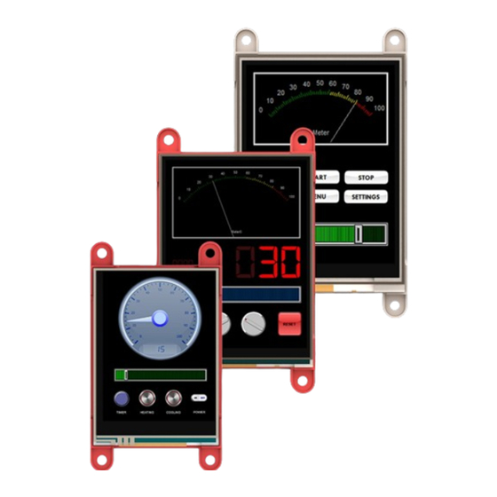
• Reference Documents The gen4-uLCD-XXPT is part of the gen4 series of display modules designed and manufactured by 4D Systems. Depending on your purchase, the modules feature either a 2.4”, 2.8" or 3.2" colour TFT LCD display, with resistive or capacitive touch. -
Page 4: System Requirements
Note: microSD Card is optional and is only needed with projects that are utilizing graphical files. Please note as well that not all cards on the market are SPI compatible, and therefore not all cards can be used in 4D Systems products. Buy with confidence, choose the cards recommended by 4D Systems. - Page 5 Simply lay the display out with the objects you want (similar to ViSi), set the events to drive them and the code is written for you automatically. ViSi-Genie provides the latest rapid development experience from 4D Systems. ViSi A visual programming experience that enables drag-and-drop type placement of objects to assist with 4DGL code generation and allows the user to visualize how the display will look while being developed.
-
Page 6: Connecting The Display Module To The Pc
Install Workshop4 Download links for the WS4 installer and installation guide can be found on the Workshop4 product page. CONNECTING THE DISPLAY MODULE TO THE PC This section shows the complete instructions for connecting the display to the PC. There are three (3) options of instructions under this section, as shown in the image below. -
Page 7: Connection Options
Connection Options Option A – Using the 4D Programming Cable 1. Connect one end of the FFC to your module's 30-way ZIF socket with the metal contacts on the FFC facing up on the latch. 2. Connect the other end of the FFC to the 30-way ZIF socket on the gen4-IB with the metal contacts on the FFC facing up on the latch. -
Page 8: Using The 4D-Upa
Option C – Using the 4D-UPA 1. Connect one end of the FFC to your module’s 30 way ZIF socket with the metal contacts on the FFC facing up on the latch. 2. Connect the other end of the FFC to the 30-way ZIF socket on the 4D- UPA with the metal contacts on the FFC facing up on the latch. - Page 9 6. Click on the COMMS tab, select the COM port the display module is connected to from the dropdown list. 7. Click on the RED Dot to start scanning for the display module. A YELLOW dot will show while scanning. Make sure that your module is connected properly.
-
Page 10: Getting Started With A Simple Project
GETTING STARTED WITH A SIMPLE PROJECT After successfully connecting the display module to the PC using your programming module, you can now start creating a basic application. This section shows how to design a simple user interface using the ViSi-Genie environment and utilizing the slider and gauge widgets. - Page 11 Add a Slider Widget To add a slider widget, simply click on the Home tab and choose the Inputs Widgets. From the list, you may choose the type of widget that you want to use. In this case, the slider widget is selected. Simply drag-and-drop the widget towards the What-You-See-Is-What-You-Get (WYSIWYG) section.
- Page 12 Link the Widget Input widgets can be configured to control an output widget. To do this, just click on the input (in this example, the slider widget) and go to its Object Inspector Section and click the Events Tab. There are two events available under the events tab of an input widget - OnChanged and OnChanging.
- Page 13 Build and Compile the Project To Build/Upload the project, click the (Build) Copy/Load icon. Copy the Required Files to the microSD Card Graphics data for the widgets will actually be stored to a microSD card, which will be accessed by the graphics processor of the display module during runtime.
- Page 14 Test the Application The application should now run on the display module. The slider and gauge widgets should now be shown. Start touching and moving the thumb of the slider widget. A change in its value should also result to a change in the value of the gauge widget, since the two widgets are linked.
-
Page 15: Workshop4 Pro
(i.e. Arduino) interfaced to a 4D Systems display. Genie Magic brings the ability to add standard 4DGL code to various points within the ViSi-Genie environment. This enables you to have all the advantages of ViSi-Genie but with the new ability to add extra 4DGL where you want it. -
Page 16: Application Notes
APPLICATION NOTES Supported App Note Title Description Environment 4D-AN-00117 Designer This application note shows how to Designer Getting Started create a new project using the - First Project Designer Environment. It also introduces the basics of 4DGL (4D Graphics Language). 4D-AN-00119 ViSi Getting This application note shows how to... -
Page 17: Reference Documents
Designer, ViSi, or Serial environment is recommended. ViSi and Designer allow users to write the code for their applications. The programming language used with 4D Systems graphics processors is called "4DGL". The Serial environment, on the other hand, transforms the display module into a slave serial device, allowing the user to control the display using any external host with a serial port. - Page 18 NOTES gen4-uLCD-XXPT - GETTING STARTED MANUAL...
-
Page 19: Glossary
6. microSD Card – a type of removable flash memory card used for storing information. 7. Processor – is a small chip that resides the 4D Systems displays. Its basic job is to receive input and provide the appropriate output. -
Page 20: Software
10. WYSIWYG – What-You-See-Is-What-You-Get. The Graphics Editor Section in Workshop4 where the user can drag and drop widgets. Visit our website at: www.4dsystems.com.au Technical Support: www.4dsystems.com.au/support Sales Support: sales@4dsystems.com.au Copyright © 4D Systems, 2019, All Rights Reserved gen4-uLCD-XXPT - GETTING STARTED MANUAL...
Need help?
Do you have a question about the gen4-uLCD-28PT and is the answer not in the manual?
Questions and answers