Table of Contents
Advertisement
Advertisement
Table of Contents

Related Manuals for CLIVET ELFOControl2


Summary of Contents for CLIVET ELFOControl2
- Page 1 ELFOControl Installation, configuration and use manual 16-12-2013 M0CZ40B12-10...
- Page 2 Clivet is being working for years to offer systems able to assure the maxi- mum comfort for long time with high reliability, efficiency , quality and sa- fety.
- Page 3 TABLE OF CONTENTS INSTRUCTIONS FOR USER Main functions ..............................pag.5 Display ................................pag.6 Switching on and off the system ........................pag.7 Heating / cooling / automatic mode ......................... pag.8 Adjusting date and hour ..........................pag.9 Heat pump ..............................pag.10 Domestic hot water ............................pag.14 Fresh air: ELFOFresh ............................
- Page 5 MAIN FUNCTIONS Main functions of the System. Indications for the use Heat pump for: Keep this manual in an accessible place for the operator. • hot and cold water for radiators, radiant panels and fan convectors; In case of breakdown or malfunction: •...
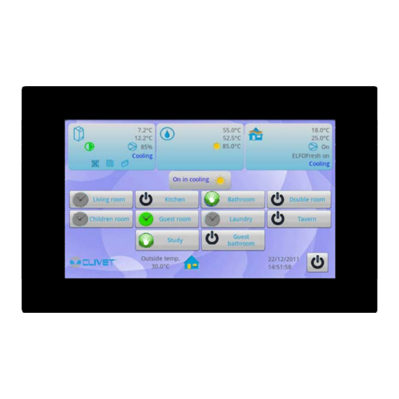
- Page 6 DISPLAY Information displayed: status of the system: heating / cooling / automatic / off date/hour Domotic control: green = connected system gray = system configuration (not connected); parameter not enabled Outdoor air temperature Heat pump supply water temperature return water temperature % use of the compressor status components found in the system:...
- Page 7 SYSTEM START-UP AND SWITCH-OFF 1 - The system can be: • • • off until day / off until time a select 3 - Start up the system 4 - Switch off the system 5 - Switch off the system until day / hour: at the due time, the system returns to the status previously set.
- Page 8 SYSTEM CHANGE MODE 1 - Operation of the system. select Select: 2 - Heating only 3 - Cooling only 4 - Automatic switches from heating to cooling automatically, depending on the outdoor and indoor temperature detected mode enabled only if ELFOFresh , is present Confirm the modification Page 8...
- Page 9 SYSTEM ADJUSTING DATE AND HOUR Set date and hour to synchronise the system operation. select Settings: • Automatic (do not activate this setting) • Set date • Select time zone • Set hour • Use H24 format • Select date format select To exit drag area "3"...
- Page 10 HEAT PUMP SET HEAT PUMP OPERATION Information displayed: • supply water temperature • return water temperature • % capacity of the compressor • operation status (heating/cooling/off) • components found in the system (radiators, fan coils and radiant panels) and relative status (enabled / excluded). select 2 - Automatic operation: The heat pump is used to produce both air-conditioning system...
- Page 11 HEAT PUMP CLIMATE SETTINGS Set the operation set point of each circuit: • winter or summer, • fixed or compensated 2 - Hydraulic circuits of the system: select Select the single circuit to customise the set point 3 - Set point regular intervals: Winter Summer 4 - Supply water set point:...
- Page 12 HEAT PUMP CHANGE OF SET POINT, FROM FIXED TO COMPENSATED 1 - Select the single circuit to customise the set point 2 - Select "fix" select 3 - Compensated supply water set point: • set the compensation curve that corrects the water set point value, depending on the outdoor air temperature value.
- Page 13 HEAT PUMP MODIFY THE OUTDOOR TEMPERATURE: 5 - select 6 - Set the required values: Max 35°C Min. 22°C MODIFICATION OF 4 POINTS 7 - Modify the correction select select 8 - Modify the correction example: + 2°C The correction can be used to modify the climatic curve rapidly, without modifying the 4 set points.
- Page 14 DOMESTIC HOT WATER Information displayed: • upper storage temperature • lower storage temperature • solar water temperature DOMESTIC HOT WATER OPERATION 2 - Automatic operation: select domestic hot water is produced automatically, according to the requirement, using all the resources available. 3 - With thermal solar system only: the storage tank temperature is ensured only using solar collectors, even with a greater set point.
- Page 15 DOMESTIC HOT WATER Programming example: Day: Friday Program: Circulation program 1 Operation Profile: start set point end time mode time (previous page) Maintenance ref. 8 Recharge and recirculation ref. 7 + ref. 11 Maintenance ref. 8 Maintenance and ref. 8 + ref. 11 recirculation Maintenance ref.
- Page 16 ELFOFRESH FRESH AIR Information displayed: • supply air temperature • return air temperature • status of the compressor: on/off • Elfofresh on / off • operation status: heating / cooling / ventilation off If 4 units are available, data of unit 1,2,3 and 4 are displayed alternatively.
- Page 17 ELFOFRESH PROGRAMMING Provide fresh air depending on a daily time schedule. 5 preset daily programs are available (max 14 programs). All programs can be modified. A different program can be combined to each unit. Operation mode: optimal fresh air. Normal: To be used in case rooms are occupied.
- Page 18 "AWAY FROM HOME" CONTROL The "away from home" control mode can be activated when the room is not occupied. The "Away fom home" control allows setting the operation of: • climatic zones • fresh air unit • domestic hot water select "AWAY FROM HOME"...
- Page 19 ZONE SCHEDULING The operation of every area can be SCHEDULED or MANUAL. Scheduled zone in temperature Scheduled zone in call Zone off Manual zone in temperature Manual zone in call 2 - Scheduled zone : uses one of the 7 preset programs. select 3 - Zone managed in manual mode: The programming can be ignored and the area forced for a determined...
- Page 20 ZONE SCHEDULING 7 - Select: • winter or summer season • The day of the week to be programmed: the selected day is highlighted in grey. • summer or winter program among those available The temperature of the “Comfort” profile is preset for all the house areas: •...
- Page 21 ZONE SCHEDULING Set: • temperature difference compared to the "Comfort" mode • humidity % • automatic / manual / silenced / off ventilation Example Summer Comfort difference Economical Temperature 25 °C +2 °C 27°C Winter Comfort difference Economical Temperature 21 °C -2 °C 19°C Temperature must be selected for both Summer and Winter (section 7)
- Page 22 ZONE SCHEDULING Modification of a single component temperature select 2 - set temperature living room = 25°C. 3 - temperatures detected by thermostats 4 - correction setting cursors Example sub-areas correction of the Final temperature area set point Living room 2 + 4.5°C 29.5°C Main entrance...
- Page 23 ALARMS Alarms are indicated by the symbol: Alarms are saved in the memory. Example: • heat pump in alarm or system main alarm select select 4- description of the alarm and date/hour of the event Attention: Before resetting an alarm, identify and remove the cause generating that.
- Page 24 MODIFICATION OF THE PROGRAM NAME Names of the following programs can be customised: • Domestic hot water • Elfofresh • Zone select select select press for 2 sec Page 24...
- Page 25 MODIFICATION OF THE PROGRAM NAME select Use the keyboard to type the name of the program. Key functions: Capital or small letters Numbers Space Delete Confirm Page 25...
- Page 26 SYSTEM SETTINGS Access to the “System settings” is reserved only to the After sales Centre It allows setting: 2 - Parameters 3 - System layout 4 - Elfocontrol select Page 26...
- Page 27 INSTRUCTIONS FOR THE INSTALLER GENERAL WARNINGS Regulations The information contained in this manual must be integrated with current statutory regulations and by the standards of good practice. Operate with the safety regulations in force. Planning The water and electric system must be determined by the system designers in accordance with the regulation in force.
- Page 28 ELFOCONTROL CIECX Uncased box (optional) micro SD system configuration data Page 28...
- Page 29 ELFOCONTROL Ethernet UTP cat.5 cable 5 m (supplied with ELFOControl ELFOControl power supply (max 90 mt) Bus RS 485 (Customer, option CBSX 50 mt. spool) feeder 12Vdc (supplied with ELFOControl converter Ethernet/485 (supplied with ELFOControl not used converter 485 - TCP/IP - 12...24 Vdc o 12 Vac USB port domotic system (Customer) system restart...
- Page 30 BUS RS485 SHIELDED CABLE SERIAL LINE INSTALLATION OF THE SERIAL LINE • • • 50-metre spool (optional CBSX) Maximum number of components: 40 Performed by trained and qualified personnel in data communication networks • • Pair of twisted and shielded conductors Maximum length of every single serial line •...
- Page 31 SYSTEM DIAGRAMS SYSTEM TYPICAL DIAGRAMS: NEW BUILDING WITH RADIANT PANELS AND RADIATORS Ethernet/485 Converter SYSTEM TYPICAL DIAGRAMS: NEW BUILDING WITH RADIANT PANELS, FAN COILS AND RADIATORS Ethernet/485 Converter Indicative diagram The components of the system are not indicated, because they must be specified by both the Designer and Installer (e.g. expansion tanks, vents, cocks, calibration/safety valves, etc.) Page 31...
- Page 32 SYSTEM DIAGRAMS SYSTEM TYPICAL DIAGRAMS: REQUALIFICATION OF THE EXISTING BUILDING WITH RADIANT PANELS AND RADIATORS Ethernet/485 Converter SYSTEM TYPICAL DIAGRAMS: REQUALIFICATION OF EXISTING BUILDING WITH RADIATORS Ethernet/485 Converter Indicative diagram The components of the system are not indicated, because they must be specified by both the Designer and Installer (e.g. expansion tanks, vents, cocks, calibration/safety valves, etc.) Page 32...
- Page 33 UNIT FOR PRODUCING THERMAL AND COOLING ENERGY GAIA ARIA GAIA ACQUA ELFOENERGY GROUND MEDIUM MSER-XEE 31-61 R-410A WSHR-XEE 31-61 R-410A WSHN-XEE 82-802 Version AC Version AC GAIA MAXI ARIA GAIA MAXI ACQUA MSER-XIN 61 R-410A WSHR-XIN 61 R-410A TERMINATION JUMPER Ethernet/485 Converter 12VDC...
- Page 34 UNIT FOR PRODUCING THERMAL AND COOLING ENERGY HORUS HORUS HORUS WSAR-MT-E 21-81 R-407C WSAR-MT-E 21-81 R-407C WSAR-HT-E 31-81 R-407C For outdoor installation For indoor installation For outdoor installation HORUS WSAR-HT-E 31-81 R-407C For indoor installation TERMINATION JUMPER Ethernet/485 Converter 12Vdc RS485 ETHERNET Terminazione...
- Page 35 UNIT FOR PRODUCING THERMAL AND COOLING ENERGY ELFOENERGY EXTENDED INVERTER WSAN-XIN 21-71 R-410A TERMINATION JUMPER Ethernet/485 Converter 12Vdc RS 485 ETHERNET Terminazione CMSC2X - Serial communication module with RS485 serial converter kit- optional Page 35...
- Page 36 UNIT FOR PRODUCING THERMAL AND COOLING ENERGY VULCAN GROUND MEDIUM WBAN 41-81 R-407C WSH/N-EE17-121 R*410A WSAN/T-XEE 82-302 R-410A TERMINATION JUMPER Ethernet/485 Converter 12Vdc RS 485 ETHERNET Terminazione CMMBX - Serial communication module with supervisor (MODBUS) - optional Page 36...
- Page 37 FRESH AIR UNIT ELFOFRESH ELFOFRESH ELFOFRSH LARGE CPAN-U 70-120 R134a CPAN-U 200-650 R410a CPAN-U 17-51 R410a TERMINATION JUMPER Ethernet/485 Converter 12Vdc RS 485 ETHERNET Terminazione SP1X - RS485 serial port for remote communication - optional Page 37...
- Page 38 AMBIENT TERMINALS ELFOROOM ELFOROOM ELFOROOM OUTVOT 3-15 INVOT 3-15 OUTVOT 3-15 ELFOROOM INVOT 3-15 TERMINATION JUMPER Ethernet/485 Converter SERIAL CARD Set as shown in the figure Terminazione Page 38...
- Page 39 CLIVET TALK TERMINAL SPACE 230V 12Vdc ETHERNET SP1X - RS485 serial port for remote communication - optional (page 29) Terminazione CTS- CLIVET TALK TERMINAL SPACE Electronic for HID-T2 or HID-T3 thermostats CLIVET TALK TERMINAL SPACE (ELFOControl ) - optional Page 39...
- Page 40 CLIVET TALK TERMINAL SPACE 230V 12Vdc ETHERNET SP1X - RS485 serial port for remote communication - optional (page 29) Terminazione CTS- CLIVET TALK TERMINAL SPACE Electronic for HID-T2 or HID-T3 thermostats CLIVET TALK TERMINAL SPACE (ELFOControl ) - optional Page 40...
- Page 41 SYSTEM ACCESSORIES Termostats Elfocontrol Elfocontrol HID-T2X 222x43x168 LxHxP HID-T2 local electronic room control device (temperature only); 127x86x27 LxHxP 230/1/50 feeder - 12Vdc 4 DIN modules HID-TI2X HID-Ti2 local electronic room control device (uncased, temperature only); In built-in 503 box Ethernet/485 converter 3 DIN modules HID-T3X HID-T3 local electronic room control...
- Page 42 SYSTEM ACCESSORIES MODULE OF RADIANT AREAS WITH HID-T2, HID-TI2 and HID-T3 CLIVETBUS THERMOSTATS Example on how to use: Step management Thermostat 1 controls one area with 1 component Double step management Thermostat 4 controls one area with 2 components Radiator management Thermostat 6 controls the valve for the heated towel rails G1 G0 G6..
- Page 43 SYSTEM ACCESSORIES MODULE OF RADIANT AREAS WITH HID-TI4 and HID-UR UNCASED MODBUS THERMOSTATS The thermostats run only if combined with the radiant module. Set as indicated in the figure Example on how to use: Step management The thermostat + relative humidity probe 1 - 2 - 3 controls one area with 1 component RS485 Double step management The thermostat + relative humidity probe 4 controls one area with 2 components...
- Page 44 SYSTEM ACCESSORIES THE RADIANT ZONE MODULE CONTROLS THE HEATED TOWEL RAIL VALVE Example of use: Step management Thermostat 5 controls the radiant panel Radiator management The heated towel rails is managed by the zone scheduling (page 19) The function is supported only with thermostats HiD-T2, HiD-Ti2 and HiD-T3 RS485 BT2 COM CH 1...
- Page 45 SYSTEM COMPONENT CONFIGURATION RADIANT ZONE MODULE - CONFIGURATION The radiant zone module must be configured via thermostat depending Parameters to be modified on the components connected to the outputs. Channel Parameter Value 0 = Disabled 1 = Thermoregulation 1G 2 = Thermoregulation 2 G 3 = I/O ..
- Page 46 20C° from the calculation, in order to not affect the water temperature inside the entire system and the head closes. 0 = Clivet If thermostat model =1 (Modbus KBlue thermostats) the parameters 1070 from P02 to P07 cannot be set at 5 or 6.
- Page 47 SYSTEM COMPONENT ADDRESSING ADDRESSING Each unit inside the network is recognised thanks to an address. The address must be stored in the memory of the unit using a keyboard or thermostat. Serial addressing Domestic hot water module * The addresses 17,18 and next are used both for terminals and for the single zone Heat pump modules (page 56).
- Page 48 SYSTEM COMPONENT ADDRESSING HORUS Parameters to be modified Mnemonic Parameter Description Value Name ModBus supervision serial Index address Baud Rate (0=4800 / 1=9600 Baud Rate 2 =19200) Parity 0=NO / 1=Odd 2=Even Parity supervision serial Enter the Maintenance operator password to access the parameters. Main Menu Stata Press.
- Page 49 SYSTEM COMPONENT ADDRESSING WSAN-XIN Parameters to be modified Parameters Description Value CF30 ModBus protocol controller Address ModBus protocol Baud Rate (2=4800 / 3=9600 CF31 4 =19200) CF32 Parity modbus 1=EVEN / 2=NONE / 3=ODD DI4 Digital input Configuration CL43 ( remote OFF) DI5 Digital input Configuration CL44 (remote Summer / Winter )
- Page 50 SYSTEM COMPONENT ADDRESSING ELFOENERGY / ELFOFRESH Units can be CPAN-U 70-650 (Elfofresh ) and / or CPAN-U 17-51 (ElfoEnergy) if one unit is present: address = 3 if four units are presents: First unit address = 3 Second unit address = 4 Third unit adress = 5 Fourth unit adress = 6 ELFOEnergy - Parameters to be modified...
- Page 51 SYSTEM COMPONENT ADDRESSING TERMINALS, AREAS MODULES WITH HID-T2, HID-T3 THERMOSTATS Parameters to be modified HID-T2 Temperature / HID-T3 Temp. + humidity Mnemonic Parameter Description Value Name Index Device address 17,18..Baud Rate 0=4800 1 :9600 Baud Rate 2 :19200 Parity 0=NO / 1=Odd 2=Even Parity supervision serial First address the area modules combining them with the lowest addresses (example area module 17 - terminals 18 ....)
- Page 52 SYSTEM COMPONENT ADDRESSING TERMINALS, AREA MODULES WITH HID-TI2 THERMOSTATS Parameters to be modified HID-TI2 Uncased temperature Mnemonic Parameter Description Value Name Index Device address 17,18..Baud Rate 0=4800 1 :9600 Baud Rate 2 :19200 Parity 0=NO / 1=Odd 2=Even Parity supervision serial First address the area modules combining them with the lowest addresses (example area module 17 - terminals 18 ....) If the number of fancoils + area modules in the system is greater than 33, use addresses 60, 61, etc.
- Page 53 SYSTEM COMPONENT ADDRESSING HID-TI4 and HID-UR THERMOSTATS Thermostat addressing HID-TI4 Uncased temperature Channel Flashings The thermostat runs only if combined with the radiant module. 1 - Supply and keep the addressing key pressed until it starts flashing quickly. 2 - After a few seconds, count the slow flashings up to the address to be assigned and release the button. 3 - A fast flashing at the end confirms the procedure.
- Page 54 SYSTEM COMPONENT ADDRESSING RADIANT ZONE MODULE Parameters to be modified The addressing can occur: • Via selector switches Mnemonic Parameter Description Value • Via thermostats Name Index Device address 11,12..Addressing with selector switches Example to assign address 12: Baud Rate 0=4800 1 :9600 Baud Rate 2 :19200 Selector switch A = 1, selector switch B = 2...
- Page 55 SYSTEM COMPONENT ADDRESSING MIXING MODULE Parameters to be modified Follow the instruction at page 51 or 52 Mnemonic Parameter Description Value Name Index Device address 50..,52 Baud Rate 0=4800 1 :9600 Baud Rate 2 :19200 Parity 0=NO / 1=Odd 2=Even Parity supervision serial For module RS485 see below.
- Page 56 SYSTEM COMPONENT ADDRESSING ZONE MODULE (HEATED TOWEL ) The module operation opens and closes the valve, according to the Parameters to be modified temperature detected by the thermostat, in the cooling mode, the module Mnemonic Parameter Description Value closes the valve. Name The module can be used also to control 1 radiant circuit.
- Page 57 SYSTEM COMPONENT ADDRESSING I/O MODULE System pump on the secondary and area valves RS485 230V Separator between primary and secondary circuit. 1 2 3 4 5 6 7 11 12 In the secondary circuit, a circulator is activated on energy request by the system.
- Page 58 SYSTEM COMPONENT ADDRESSING I/O MODULE Auxiliary resource control in heating mode RS485 If using just one boiler not associated with a heat pump. 230V It is activated when the system is in heating mode and one of the areas needs to be activated. 1 2 3 4 5 6 7 11 12 ON / OFF...
- Page 59 SYSTEM COMPONENT ADDRESSING I/O MODULE Module addressing To carry out the addressing, connect to bus only 1 module at a time. Set the system and put it into communication with all devices Disconnect bus (C) of module A Access to the parameter scripture mask via modbus (see sideway) Point the IO module provisionally addressed at 7 (B) At parameter 788 of module write 8 Point the IO module just addressed at 8 (B)
- Page 60 SYSTEM COMPONENT ADDRESSING DOMESTIC HOT WATER MODULE 1 min. Once powered, are displayed. Wait – – – LOAD 1 minute to load the software. For module RS485 refer to page 55 Parameters to be modified Return to main menu Mnemonic Parameter Description...
- Page 61 SYSTEM COMPONENT CONFIGURATION ELFOCONTROL - SYSTEM CONFIGURATION The configuration is performed directly on ELFOControl introducing: • type of system; • name of the climatic areas (kitchen, living room, etc.); • mixed and not mixed circuits; • units installed ( which and how many: heat pumps, terminals, etc.); •...
- Page 62 SYSTEM COMPONENT CONFIGURATION Create / modify areas: • • modify • remove select select Use the keyboard to type the name of the area. Key functions: Capital or small letters Numbers Space Delete select select Page 62...
- Page 63 SYSTEM COMPONENT CONFIGURATION select Define the hydraulic circuits: • high temperature non-mixed circuits (max. 10) Circuits greater than 4 refer to the 1st high temperature area • low temperature mixed circuits (max. 3) refer to the subsequent page Possible combinations with boosters: STD booster •...
- Page 64 SYSTEM COMPONENT CONFIGURATION Define mixed circuits: • low temperature mixed circuits (max. 3) • for combinations, refer to the previous page select Define the composition of the system: A. heat pump type B. number of Elfofresh units (max. 4) C. number of Fancoil modules (max. 40 including other components found) D.
- Page 65 SYSTEM COMPONENT CONFIGURATION Select the type of Elfofresh installed: • Elfofresh • Elfofresh • Elfofresh / Elfofresh select select A - Combine each used unit to every area. To see the other areas, drag area “1” upwards For each module available, define the type of controlled component for each channel: •...
- Page 66 SYSTEM COMPONENT CONFIGURATION Define the belonging area for each component available in the system. (radiator/fan coil) Controlled component: • Elforoom • Elfospace Local control from keyboard or thermostat Terminal of reference (master) Belonging area: • kitchen, living room, etc. Type of circuit assigned: •...
- Page 67 AUTOCONFIGURATION Check of the auto-configuration procedure end. select select Autoconfiguration completed For make the autoconfiguration changes effective, turn off and on the power TO MODULES. select Page 67...
- Page 68 AUTOCONFIGURATION If you do not see “ Autoconfiguration completed”: 1. check the element is in ON 2. check the network Page 68...
- Page 69 SYSTEM COMPONENT STATUS VERIFICATION OF THE COMPONENT COMMUNICATION Once the system is restarted and the new configuration loaded, verify the serial communication. For a correct verification, wait 5/10 minutes from the first restart, this period can vary depending on the composition of the system. select select Communication OK...
- Page 70 SYSTEM COMPONENT STATUS ZONE ELEMENTS STATUS Check of the installed radiant / fancoil / zone modules operation status. select select For reference only: A. Status on / off B. Heating/cooling C. Ambient setpoint °C D. Air temperature °C E. Ambient humidity % F.
- Page 71 SYSTEM COMPONENT STATUS For reference only: A. Circulator status on / off B. heating/cooling C. Supply water temperature °C D. Supply water temperature °C E. Return water temperature °C F. Air temperature °C G. Ambient humidity % H. Valve opening % I.
- Page 72 SYSTEM COMPONENT STATUS You can insert the contact references. select select Company…...…... Confirm Company…... Confirm the modification Page 72...
- Page 73 ERROR: RS485 NETWORK TROUBLESHOOTING 1. All the units requested do not 2. Some units requested do not 3. From a certain point on, the units do respond. respond. not communicate Verify no short-circuits occurred on the Ensure they are switched on It is likely that the bus of the first unit RS485 serial line does not communicate due to a short-...
- Page 74 PARAMETERS OF THE COMPONENTS Below, we describe the parameters that are set by the autoconfiguration on the several components of the system; the list must be consid- ered indicative and is an operative trace to be assessed, depending on the type and system configuration. GAIA (version AB and AC) - Anti-dew compensation enabling ( only in cooling) Modbus Parameter...
- Page 75 MODBUS TCP / IP System architecture The connection between Elfocontrol2 (EC2) and the home automation system is done using a device called "Sten". The home automation system must implement a modbus communication TCP/IP over ethernet connection The registers are NOT retentive, ie a possible reset voltage implies that the system update again all necessary records.
- Page 76 Areas commands For each areas you can set the commands listed in the table below. There are 7 records for each areas: first record : area 1 => 10, area 2 => 17, area 3 => 24,…, area 12 => 87 Address Description Notes...
- Page 77 Area stata For each areas you can read the data listed in the table below. There are 4 records for each area: First area : area 1 => 150, area 2 => 154, area 3 => 158,…, area 12 => 194 Address Description Notes...
- Page 80 Tel. + 31 (0) 33 7503420 - Fax + 31 (0) 33 7503424 - info@clivet.nl CLIVET GmbH Hummelsbütteler Steindamm 84, 22851 Norderstedt - Germany Tel. + 49 (0) 40 32 59 57-0 - Fax + 49 (0) 40 32 59 57-194 - info.de@clivet.com CLIVET RUSSIA Elektrozavodskaya st. 24, office 509 - 107023, Moscow, Russia Tel.
Need help?
Do you have a question about the ELFOControl2 and is the answer not in the manual?
Questions and answers