
Subscribe to Our Youtube Channel
Related Manuals for CLIVET KJRP-75A


Summary of Contents for CLIVET KJRP-75A
- Page 1 INSTALLATION & OWNER’S MANUAL In-built controller KJRP-75A PEMF00001 IA19M012ML-00 Thank you very much for purchasing our product. Before using your unit, please read this manual carefully and keep it for future reference.
-
Page 2: Table Of Contents
This manual gives detailed description of the precautions that should be brought to your attention during operation. In order to ensure correct service of the wired controller please read this manual carefully before using the unit. For convenience of future reference, keep this manual after reading it. - Page 3 2.4 Installation method 2.5 Schematic drawing of installation...
-
Page 4: Operation
1 OPERATION 1.1 Operation precautions Read the safety precautions carefully before installing, and must be obeyed. WARNING Means improper handling may lead to personal death or severe injury. CAUTION Means improper handling may lead to personal injury or property loss. This manual uses the following icons: Prohibit Follow the guide lines... -
Page 5: Operation Conditions
Do not operate by wet hand, to prevent electrical shock. Do not use pesticide, disinfectant and flammability spray materials to spray directly, otherwise will cause fire or deformation. Do not peel off the button and the cover by hand, to prevent electrical shock. -
Page 6: User Interface
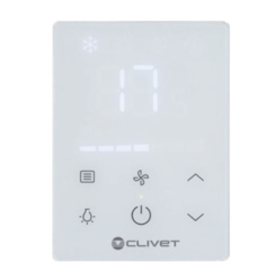
1.4 User interface Cooling Heating Dry Auto Remote Signal Receiving Area Follow Me Display Area Of the Temperature Wired Controller Fan Speed Automatic Fan Speed Fan Speed Button Mode Button Temp. Setting Button Running Indicator Backlight Button On/Off Button... -
Page 7: Instructions For Use
1.5 Instructions for use 1.5.1 Basic setting Tap Mode button The operating mode changes in the following order: Heating Auto Adjust temperature Temperature range 17°C~30°C Tap Fan Speed button Seven fan speeds and Auto available. Tap On/Off button To start the unit and send all the configured parameters. - Page 8 1.5 Instructions for use 1.5.2 "Follow Me" Operation Process The Follow Me function is disabled by default. After active the Follow Me function, controller will showing the room temp which detect by the controller self, and send the value to fancoil every 3 mins, to replace the value which detect by the room temp sensor of fancoil sensor.
-
Page 9: Further Details
1.6 Further details 1.6.1 Supplementary instructions Fan Speed button Fan speed cannot be set in Dry/Auto mode (Auto displayed). Backlight mode: Steady On: means backlight is normally on. 1 ) Tapping to start the unit can enter the backlight steady on mode. - Page 10 Fault Error Remarks Name Code PROM Error Unit stopped; unrecoverable communication error The wired controller can operate normally after the wired controller temperature sensor fails. There are two cases: (1) When the Follow Me function is enabled, Wired controller Error the E0 code is displayed temperature sensor (not displayed during...
- Page 11 Fault Error Name Remarks Code Coil sensor (T2H) Unit stopped; automatic Error port abnormal recovery after clearing DC motor stall fault Unit stopped; unrecoverable Error Main board and wired Unit stopped; automatic Error controller communication recovery after clearing error Water level exceeding Automatic recovery after Protection warning line...
-
Page 12: Installation
2 INSTALLATION 2.1 Safety precautions Read the safety precautions carefully before installing the unit. Stated below are important safety issues that must be obeyed. WARNING Please entrust the distributor or professionals to install the unit, do not install the unit by the user. Do not uninstall the unit randomly. -
Page 13: Installation Accessories
Do not connect transition or extended connection in the middle of the wirings of the wire controller. 2.2 Installation accessories Please confirm that all the following parts have been supplied. Name Remarks Wire controller Used to control the IDU main unit. Used to install the wired controller onto M4×20 Philips head screw the wall. -
Page 15: Installation Dimensions
Please install the following accessories in the filed. Name Remarks Shielded 5-core cable 1 RVVP-0.5 mm ×5, embedded into the wall Wiring tubes (insulation Embedded into the wall; maximum wiring suite) length: 15 m Big Phillips screwdriver 1 Used to install cross recessed head screws Used to remove the bottom cover of Small slotted screwdriver wired controller... - Page 16 2.4 Installation method 2.4.1 Non-wall-mounted 1. Wiring requirements The two ends of the connection cable set are different. That with the larger 5-core plug is defined as terminal A, while that with the smaller 5-core plug is defined as terminal B. Terminal A Terminal B...
- Page 17 Connect terminal A to the 5-core socket of the IDU main control board (See the figure below). Supplied connection cable set of IDU main control board IDU Main control board Terminal A 2. Insert a slotted-head screwdriver into the bottom slot of the wired controller, and rotate in the direction indicated to remove the rear cover of the wired controller.
- Page 18 3. Take terminal B out of the FCU electric control box and pass it through the wiring hole in the rear cover of the wired controller. Connect terminal B to the 5-core socket on the PCB of wired controller. Then, restore the rear cover of wired controller and install the wired controller into the FCU electric control box with the display panel face-up, as shown below.
- Page 19 2.4.2. Wall-mounted 1. Wiring requirements Cut the connection cable set in the middle (unsheathed place). The section that includes terminal A is section A, while the section that includes terminal B is section B. Connect terminal A to the 5-core socket of the IDU main control board (See the figure below).
- Page 20 5-core shielded cable embedded in the wall Section B Make sure that the five wiring terminals of the wired controller (A/B/X2/Y2/E) correspond to those of the connection cable set (accessory) one by one. The shielded layer of 5-core shielded cable must be grounded. The longest wiring length of the system is 50 m.
- Page 21 3. Pass section B of the connection cable set through the wiring hole in the rear cover of the wired controller, and fix the rear cover of wired controller on the wall using four plastic studs and the Philips head screws, as shown in the figure below.
- Page 22 Terminal B 5. Knock the front cover of wired controller into the rear cover with the bottom buckles aligned first, as shown in the figure below.
- Page 23 CAUTION During installation, reserve a suitable length of the connecting cable for the wired controller so that the wired controller can be taken down in case of maintenance. 2.5 Schematic drawing of installation Wiring with IDU: IDU electric control box 5-core shielded IDU electric cable...
Need help?
Do you have a question about the KJRP-75A and is the answer not in the manual?
Questions and answers