
Subscribe to Our Youtube Channel
Related Manuals for U-Line Combo 1000 Series


Summary of Contents for U-Line Combo 1000 Series
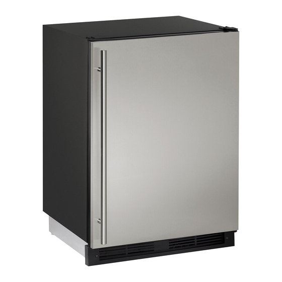
- Page 1 USER GUIDE & SERVICE MANUAL SAFETY • INSTALLATION & INTEGRATION • OPERATING INSTRUCTIONS • MAINTENANCE • SERVICE RIGHT PRODUCT. RIGHT PLACE. RIGHT TEMPERATURE. SINCE 1962. 1000 Series CO1224F 24" Combo Model ® • •...
- Page 2 USER GUIDE & SERVICE MANUAL u-line.com Table of Contents Installation Integrated Panel Dimensions Integrated Panel Installation Grille / Plinth Installation...
- Page 3 ® to preserve the right product, in the right place, at the right temperature. Since 2014, U-Line has been part of the Middleby family of brands. All products are designed, engineered, and assembled in Milwaukee, Wisconsin, USA, and select products are available worldwide.
- Page 4 USER GUIDE u-line.com SAFETY • INSTALLATION & INTEGRATION • OPERATING INSTRUCTIONS • MAINTENANCE • SERVICE Integrated Panel Dimensions 2. Optional: Stain or Finish panel to desired stain or color. Be sure to closely follow the instructions provided by INTEGRATED PANEL the manufacturer.
- Page 5 Clamp using clamps. A robust tape may also 5. Partially loosen the 3 screws, securing the top hinge to be used. U-Line the cabinet. recommends the use of bar clamps to Door/Drawer 6. Align the panel with the outside edge (opposite the...
- Page 6 USER GUIDE u-line.com SAFETY • INSTALLATION & INTEGRATION • OPERATING INSTRUCTIONS • MAINTENANCE • SERVICE 12.Using a Phillips screwdriver, place one screw into each of the 6 pilot holes and screw down. Do not overtighten screws. 13.Be sure the screws force their way past the opening on the gasket channel and sit flush against the bottom of the channel.
- Page 7 USER GUIDE u-line.com SAFETY • INSTALLATION & INTEGRATION • OPERATING INSTRUCTIONS • MAINTENANCE • SERVICE Grille - Plinth Installation REMOVING AND INSTALLING GRILLE WARNING Disconnect electric power to the unit before removing the grille. When using the unit, the grille (plinth strip/base fascia) must be installed.
Need help?
Do you have a question about the Combo 1000 Series and is the answer not in the manual?
Questions and answers