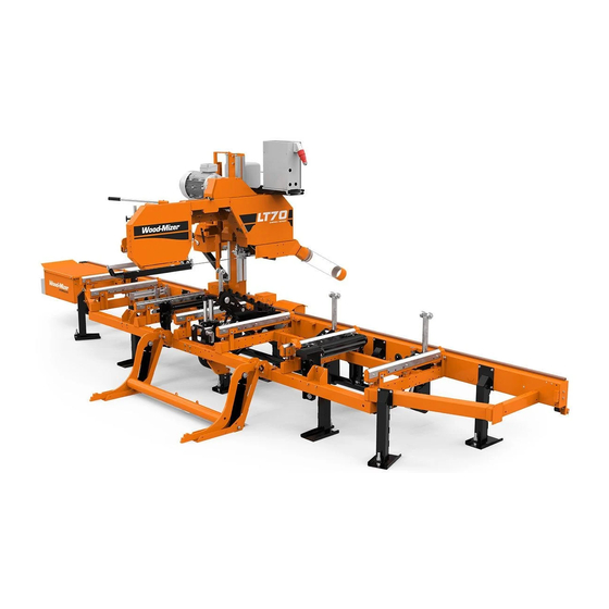
Wood-mizer LT70 Safety, Installation, Operation, Maintenance & Parts Manual
Debarker
Hide thumbs
Also See for LT70:
- Operator's manual (80 pages) ,
- Safety, operation, maintenance & parts manual (44 pages) ,
- Safety, operation, maintenance and parts manual (10 pages)
Table of Contents
Advertisement
Advertisement
Table of Contents

Subscribe to Our Youtube Channel
Related Manuals for Wood-mizer LT70


Summary of Contents for Wood-mizer LT70
- Page 1 Debarker Option Safety, Installation, Operation, Maintenance & Parts Manual LT70 Debarker rev. A.1 Safety is our #1 concern! Read and understand all safety information and instructions before oper- ating, setting up or maintaining this machine. Form #558...
-
Page 2: Table Of Contents
Table of Contents Section-Page SECTION 1 SAFETY & GENERAL INFORMATION Installation and Maintenance..................1-1 Operation and Towing....................1-2 SECTION 2 DEBARKER INSTALLATION Debarker Frame Mounting Holes................2-1 Debarker Installation ....................2-2 Wiring Instructions....................2-5 Control Component Installation ................2-6 Alignment ........................2-9 SECTION 3 OPERATION AND MAINTENANCE Locking Pin Operation .................... -
Page 3: Safety & General Information
Safety & General Information Installation and Maintenance SECTION 1 SAFETY & GENERAL INFORMATION This symbol calls your attention to instructions concerning your personal safety. Be sure to observe and follow these instructions. This symbol accompanies a signal word. The word DANGER indicates an imminently hazardous situation which, if not avoided, will result in death or serious injury. -
Page 4: Operation And Towing
DO NOT continue to operate the mill if the main key switch does not control debarker operation. Doing so could result in serious injury. Call Wood-Mizer customer service for more information. DBdoc031319 Safety & General Information... - Page 5 Safety & General Information Operation and Towing See Table 1-1. Pictogram decals used to warn and inform the user about danger in the LT15/20 Debarker. TABLE 1-1 Decal View W-M No. Description 101216 CAUTION! Read thoroughly the manual before operating the machine. Observe all safety instructions and rules when operating the sawmill.
-
Page 6: Debarker Installation
OFF (0) position, remove the key, and disconnect the sawmill battery ground terminal. Failure to do so will result in serious injury or death. The Debarker Option may be installed to the LT70 sawmills with production date 01.06.2009 and later. Debarker Frame Mounting Holes IMPORTANT! Sawmills are equipped with pre-drilled Debarker mounting holes. - Page 7 Debarker Installation Debarker Installation Debarker Installation 1. Remove the hole plugs from sawmills saw head (1). Remove the hole plug FIG. 2-1 Debarker Installation DBdoc031319...
- Page 8 Debarker Installation Debarker Installation 2. Assemble the debarker to the sawmill saw head. Align the debarker arm holes and the holes in the saw head. Insert the bolts through the debarker mounting plate holes and screw to secure in place. Route the debarker wire harness through the protective conduit and next through the saw head hole and debarker arm.
- Page 9 Debarker Installation Debarker Installation 3. Take out the wire harness from the debarker arm. Slide the debarker motor harness through one of the supplied harness clamps. See Figure 2-3. FIG. 2-3 Debarker Installation DBdoc031319...
-
Page 10: Wiring Instructions
If you have any questions, call Wood-Mizer customer service. 1. The debarker wires are pre-wired for the debarker option. The debarker wires are pre-routed and stored under a guard which is removed before debarker installation... -
Page 11: Control Component Installation
Debarker Installation Control Component Installation Control Component Installation DANGER! On electric mills, hazardous voltage inside the disconnect box, starter box, and at the electric motor can cause shock, burns, or death. Disconnect and lock out power! Follow all applicable electrical codes. DANGER! On gas/diesel mills, before performing any ser- vice to this equipment, turn the key to the OFF (0) position,... - Page 12 Debarker Installation Control Component Installation 3. Locate the two wire harnesses on the floor of the sawmill control box (one has two red wires, the second has two red and two black wires). 4. Connect the two red wires from the first harness to the debarker on/off switch. Connect the two black and the two red wires from the second harness to the debarker in/out toggle switch as shown on the picture below.
- Page 13 Debarker Installation Control Component Installation See Figure 2-6. LT70DC Control Panel Debarker Wires Connection. 3h1025 FIG. 2-6 5. Reinstall the front panel. Debarker Installation DBdoc031319...
-
Page 14: Alignment
Debarker Installation Alignment Alignment DANGER! Before performing any service to this equip- ment, turn the key to the OFF (0) position and remove the key. Failure to do so will result in serious injury or death. Following adjustments are required for proper debarker operation: The debarker blade should be centered with the sawmill blade. - Page 15 Debarker Installation Alignment See Figure 2-7. Adjust bolts to move motor and blade up or down Loosen jam Loosen motor mounting nuts bolts (4) Alignment tool Adjustment assembly posi- tioning bolts Debarker blade Sawmill blade Debarker blade thickness (7mm) FIG. 2-7 3.
- Page 16 Debarker Installation Alignment 5. Move the blade guide alignment tool on the sawmill blade and check the position of the debarker blade against the tool. If the debarker blade is not centered with the tool, you will need to adjust the debarker mount. Loosen the four debarker mounting bolts and use a mallet to adjust the debarker arm position.
-
Page 17: Operation And Maintenance
Operation and Maintenance Locking Pin Operation SECTION 3 OPERATION AND MAINTENANCE Locking Pin Operation See Figure 3-1. The debarker is equipped with a locking pin located on the debarker arm. Two hole locations are provided for the locking pin. Before operating the debarker, make sure the locking pin is removed. Turn the key switch to OFF (0) and remove the key. -
Page 18: Operation
Operation and Maintenance Operation Operation The Debarker Option allows you to remove bark from logs before cutting. DANGER! Make sure all guards and covers are in place and secured before operating the debarker option. Failure to do so may result in serious injury. DANGER! Keep all persons out of the path of moving equipment when operating the debarker. -
Page 19: Maintenance
Operation and Maintenance Maintenance Maintenance DANGER! Before performing any service to this equip- ment, turn the key to the OFF (0) position and remove the key. Failure to do so will result in serious injury or death. 1. Periodically check the flexible guard. Adjust the guard up or down so the bottom is even with the bottom of the debarker blade. - Page 20 Operation and Maintenance Maintenance WARNING! Adjusting belt spring tension (described below) is very important. Failure to do it properly will result in damage to the debarker blade motor. 3. Once a week check belt for tension and wear. Adjust or replace as necessary. To tighten the belt, turn the key switch to OFF (0) and remove the key.
- Page 21 Operation and Maintenance Maintenance 4. Once a week and after each spring replacing, check the spring tension. Use the in/out switch to pivot the debarker all the way in. Turn the key switch to OFF (0) and remove the key. Pull the debarker arm. The spring should be tensioned to allow to move the debarker arm halfway with 4,5 kg force.
- Page 22 Operation and Maintenance Maintenance 5. Once a week check the braking time. The time from switching off the debarker blade till the moment when the blade is completely stopped should be no longer than 10 seconds. If this time is longer than 10 seconds, loosen the locking nut and turn right the braking pin adjustment screw by 360 .
- Page 23 Operation and Maintenance Maintenance See Figure 3-5. FIG. 3-5 Operation and Maintenance DBdoc031319...
-
Page 24: Troubleshooting
Operation and Maintenance Troubleshooting Troubleshooting DANGER! Before performing any service to this equip- ment, turn the key to the OFF (0) position, remove the key, and disconnect the sawmill battery ground terminal. Failure to do so will result in serious injury or death. PROBLEM CAUSE SOLUTION... - Page 25 Operation and Maintenance Troubleshooting Operation and Maintenance DBdoc031319...
- Page 26 Operation and Maintenance Troubleshooting 3-10 DBdoc031319 Operation and Maintenance...
- Page 27 Operation and Maintenance Troubleshooting Operation and Maintenance DBdoc031319 3-11...
-
Page 28: Debarker Parts
Poland at +48-63-2626000 or +48-3912-1319. From the continental U.S., call 1-800-448-7881 to order parts. Have your customer number, vehicle identification number, and part numbers ready when you call. From other international locations, contact the Wood-Mizer distributor in your area for parts. -
Page 29: Blade Motor Assembly, Lt70Ac
Debarker Parts Blade Motor Assembly, LT70AC Blade Motor Assembly, LT70AC 3h1012b DESCRIPTION ( Indicates Parts Available In Assemblies Only) PART # QTY. DEBARKER, LT70 AC 100915 DEBARKER ARM, HORIZONTAL See Section 4.5 In/Out Motor Drive 100912-1 Assembly DEBARKER BLADE DRIVE ASSEMBLY... - Page 30 Debarker Parts Blade Motor Assembly, LT70AC Motor, AC Debarker Electric 096777 Guard, Blade Debarker Upper 096244-1 Bushing, AC Debarker Clamp 096088 Blade, 7In Dia Debarker 021236 Bushing, AC Debarker Clamp 096087 Washer, Debarker Zinc 096238-1 Guard, Blade Debarker Lower 096245-1 Bracket, AC Debarker Motor Mount Painted 096780-1 Plate, Debarker Motor Mounting...
-
Page 31: Blade Motor Assembly, Lt70Dc
22 23 22 23 3h1013 b 3h1013 b DESCRIPTION ( Indicates Parts Available In Assemblies Only) PART # QTY. DEBARKER, LT70 DC 100916 DEBARKER ARM, HORIZONTAL See Section 4.5 In/Out Motor Drive 100912-1 Assembly DC DEBARKER BLADE DRIVE ASSEMBLY 100922... - Page 32 Debarker Parts Blade Motor Assembly, LT70DC Motor, 0.75HP 12VDC Current AP Debarker Drive 100918 Bracket, DC Debarker Motor 097493-1 Guard, Blade Debarker Upper 097499-1 Washer, m5, flat zinc F81052-1 Bolt, M6X20MM, HH, Full Thread, Zinc F81001-2 Bushing, Debarker Clamp 097496 BLADE, 180 B-06.5/5.0 D-25.5 - COMPLETE 083848-1 Bushing, Blade Mounting...
-
Page 33: In/Out Motor Drive Assembly
Debarker Parts In/Out Motor Drive Assembly In/Out Motor Drive Assembly 35 14 3h1019a DESCRIPTION ( Indicates Parts Available In Assemblies Only) PART # QTY. DEBARKER ARM, HORIZONTAL 100912-1 BEARING, 6205 2RS 091804 TUBE, SPACER 098491-1 BEARING, 51305 AXIAL 098597 ARM, DEBARKER 098626-1 BOLT,M10X35-8.8 HEX HEAD FULL THREAD ZINC F81003-17... - Page 34 Debarker Parts In/Out Motor Drive Assembly NUT, M6, HEXAGON, FREE, GRADE 5(8.8) ZINC F81031-1 PIN, DEBARKER 098593-1 BEARING, HK 1412 NEEDLE 098595 RING, Z15 SNAP F81090-2 WASHER, 13 ZINC FLAT F81056-1 NUT, M12, HEXAGON, NYLON, ZINC, LOCK F81034-2 BUSHING, DEBARKER SPACER ZINC 089949-1 TENSIONER WELDMENT, DEBARKER IN/OUT MOTOR PAINTED 089969-1...
-
Page 35: Wider Debarker Assembly
Debarker Parts Wider Debarker Assembly Wider Debarker Assembly REF. DESCRIPTION ( Indicates Parts Available In Assemblies Only) PART# LT70 AC DEBARKER - WIDER 525865 LT70 DC DEBARKER - WIDER 525864 ARM, DEBARKER HORIZONTAL 525867-1 Debarker Parts doc031319... - Page 36 Debarker Parts Wider Debarker Assembly REF. DESCRIPTION ( Indicates Parts Available In Assemblies Only) PART# BEARING, 6205 2RS BALL 091804 RING, SPACER 098491-1 BEARING, 51305 THRUST 098597 ARM, DEBARKER SWING 526624-1 PLATE, SPRING BUSHING 098592-1 SPRING, DEBARKER RETAINING 098605 PIN, 3/8X2 1/4 SQ WIRE LOCK 014151 ARM WELDMENT, DEBARKER 098626-1...
- Page 37 Debarker Parts Wider Debarker Assembly REF. DESCRIPTION ( Indicates Parts Available In Assemblies Only) PART# GUARD ASSEMBLY 519064 PLATE, GUARD 519061-1 WASHER, 8.4 FLAT ZINC F81054-1 WASHER, 8.2 SPLIT LOCK ZINC F81054-4 BOLT, M8X16-8.8-B HEX HEAD FULL THREAD ZINC F81002-20 BUSHING, 9/13-40.5 519067-1 WASHER, 8.2 SPLIT LOCK ZINC...
-
Page 38: Ac Debarker Blade Drive
Debarker Parts AC Debarker Blade Drive AC Debarker Blade Drive REF. DESCRIPTION ( Indicates Parts Available In Assemblies Only) PART# DRIVE ASSEMBLY, AC DEBARKER BLADE 096239 MOTOR, STKG71X-2C IMB5 AC DEBARKER 096777 GUARD, DEBARKER BLADE UPPER 096244-1 4-11 doc031319 Debarker Parts... - Page 39 Debarker Parts AC Debarker Blade Drive REF. DESCRIPTION ( Indicates Parts Available In Assemblies Only) PART# BUSHING, CLAMPING 096088 BLADE, 180 B-06.5/5.0 D-25.5 - COMPLETE 083848-1 BUSHING, RETAINING 096087 WASHER 096238-1 GUARD, DEBARKER BLADE LOWER 096245-1 BRACKET, DEBARKER MOTOR MOUNT 096780-1 PLATE, DEBARKER MOTOR MOUNT 089551...
-
Page 40: Dc Debarker Blade Drive
Debarker Parts DC Debarker Blade Drive DC Debarker Blade Drive REF. DESCRIPTION ( Indicates Parts Available In Assemblies Only) PART# DRIVE ASSEMBLY, DC DEBARKER BLADE 100922 BRACKET, DC DEBARKER MOTOR MOUNT 097493-1 MOTOR, 0.75HP/1550 r.p.m. 12V DC 100918 4-13 doc031319 Debarker Parts... - Page 41 Debarker Parts DC Debarker Blade Drive REF. DESCRIPTION ( Indicates Parts Available In Assemblies Only) PART# GUARD, DEBARKER BLADE UPPER 097499-1 WASHER, 6.4 FLAT ZINC F81053-1 BOLT, M6X20 8.8 HEX HEAD FULL THREAD ZINC F81001-2 BUSHING, CLAMPING 097496 BLADE, 180 B-06.5/5.0 D-25.5 - COMPLETE 083848-1 BUSHING, MOUNTING 097495...
Need help?
Do you have a question about the LT70 and is the answer not in the manual?
Questions and answers