Advertisement
Quick Links
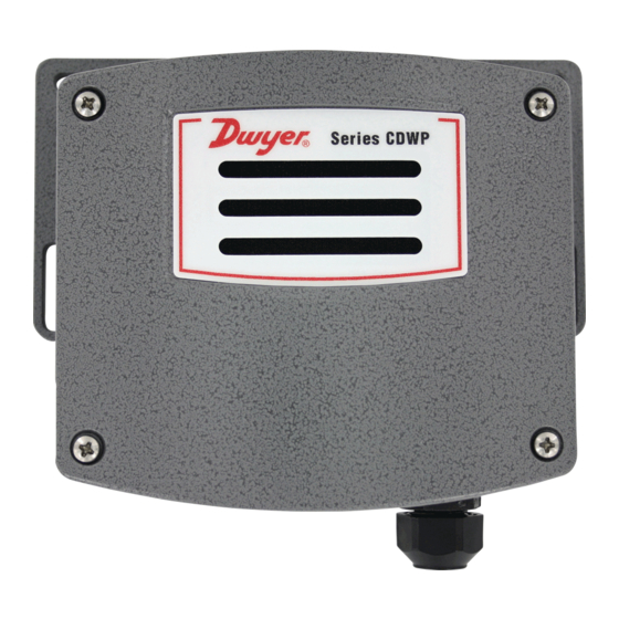
Series CDWP Carbon Dioxide Transmitter
Specifications - Installation and Operating Instructions
The Series CDWP Carbon Dioxide Transmitter accurately monitors the CO
concentration in industrial and indoor environments to help achieve energy savings.
For increased sensor life and accuracy, a single-beam dual-wavelength non-dispersive
infrared (NDIR) sensor is used to eliminate light source aging effects. The single-
beam dual-wavelength sensor technology provides the highest level of accuracy
compared to Automatic Baseline Correction methods, which can unintentionally shift
the calibration based on CO
levels and barometric pressure conditions.
2
Universal outputs allow users to select the transmitter output to be 4-20 mA, 0-5
VDC, or 0-10 VDC to work with virtually any building management controller or
programmable logic controller.
The CDWP utilizes a rugged IP54 aluminum housing with an exterior gray finish coat
that was tested to withstand a 168 hour salt spray corrosion test. This ruggedized
housing helps to protect the sensor from splashing liquid and airborne dust or debris
making the Series CDWP a great fit for animal husbandry applications and confined
feeding operations.
Single-beam dual-wavelength sensor advantages:
• Automatically corrects for aging effects in occupied and unoccupied spaces
• Measures actual unfiltered light intensity directly
• Eliminates error from incorrect assumptions of gas concentration in theoretical
logic assumption methods
INSTALLATION
Disconnect power supply before installation to prevent electrical
WARNING
shock and equipment damage
Make sure all connections are in accordance with the job wiring diagram and in
accordance with national and local electrical codes. Use copper conductors only.
Use electrostatic discharge precautions (e.g., use of wrist straps)
CAUTION
during installation and wiring to prevent equipment damage.
Do not exceed ratings of this device, permanent damage not
CAUTION
covered by warranty may result.
Upon powering the transmitter, a warm up period of 30 minutes
NOTICE
is required for the transmitter to adjust to the current CO
concentration.
DWYER INSTRUMENTS, INC.
P.O. BOX 373 • MICHIGAN CITY, INDIANA 46360, U.S.A.
(OPTIONAL
4-11/32
SUSPENSION
[110.32]
BRACKET)
11/16 [17.46]
8 X Ø3/16
[4.76]
4 X 3/4
[19.05]
6 [152.40]
SPECIFICATIONS
2
Sensor: Single beam, dual-wavelength NDIR.
Range: CO
: 0 to 2000, 0 to 5000, or 0 to 10000 PPM (depending on model).
2
Accuracy: CO
: ±40 PPM ±3% of reading.
2
Temperature Dependence: ±8 PPM/°C at 1100 PPM.
Non-Linearity: 16 PPM.
Pressure Dependence: 0.13% of reading per mm of Hg.
t
Response Time: 300 s (
).
63
Temperature Limits: 32 to 122°F (0 to 50°C).
Humidity Limits: 10 to 95% RH (non-condensing).
Power Requirements: 16-35 VDC or 19-28 VAC.
Power Consumption: Average: 2 W; Peak: 3.75 W.
Output: Current: 4-20 mA (max. 500 Ω); Voltage: 0-5 VDC or 0-10 VDC (min. 500
Ω).
Enclosure Rating: IP54.
Mounting Orientation: Vertically, with electrical connection pointing downwards.
Weight: 26.24 oz (744 g).
Agency Approvals: CE.
SUSPENSION MOUNTING
To suspend the CDWP from the ceiling, loop the end of the power cord and feed it
through the hole at the base of the bracket and hook the loop on the prong.
Figure 1: CDWP suspension bracket
M12 Connector Option
The M12 Connection option allows for easy removal of the CDWP before site cleaning
2
operations.
Figure 2: Diagram of M12 connector
Phone: 219/879-8000
Fax: 219/872-9057
Bulletin AQ-CDWP-2
Ø1/4 [6.35]
2-1/32
5-5/32
[51.59]
[130.96]
1-27/32
4-13/16
[46.82]
[122.23]
1-6 MM OR 5-10 MM
2-5/16
CABLE GLAND
[58.73]
(OPTIONAL
4-6 MM OR 6-8MM
M12 CONNECTION)
M12 CONNECTOR
FITS 4-6MM OR
6-8MM CABLE
www.dwyer-inst.com
e-mail: info@dwyermail.com
Advertisement

Related Manuals for Dwyer Instruments CDWP Deries


Summary of Contents for Dwyer Instruments CDWP Deries
- Page 1 CO operations. concentration. M12 CONNECTOR FITS 4-6MM OR 6-8MM CABLE Figure 2: Diagram of M12 connector DWYER INSTRUMENTS, INC. Phone: 219/879-8000 www.dwyer-inst.com P.O. BOX 373 • MICHIGAN CITY, INDIANA 46360, U.S.A. Fax: 219/872-9057 e-mail: info@dwyermail.com...
- Page 2 Power Supply Remote Display Choose a power supply with a voltage and current rating sufficient to meet the power The Series CDWP menu parameters can be set up and configured using a remote specifications under all operating conditions. If the power supply is unregulated, make display tool, A-449.
- Page 3 Menu Descriptions Relay on set point Humidity low output range (Series CDTR only) Sets the CO concentration which the optional relay is energized. Sets the humidity for the lowest output (4 mA or 0 VDC). Low limit: 0 PPM Low limit: 0.0% Factory setting: 1000 PPM...
- Page 4 Return Materials Authorization number (RMA) before shipping the product back for repair. Be sure to include a brief description of the problem plus any additional application notes. ©Copyright 2020 Dwyer Instruments, Inc. Printed in U.S.A. 9/20 FR# 444411-10 DWYER INSTRUMENTS, INC.
Need help?
Do you have a question about the CDWP Deries and is the answer not in the manual?
Questions and answers