Page 1
Technology that inspires Operating Instructions Control card TS002 Control card TS003 Control card TS004 980-200117001 / EN 11/2007...
Page 2
WEISS GmbH reserves the right to make alterations to this documentation (also without prior notice). WEISS GmbH is not liable for any technical or printing errors in this document. We accept no liability for damages directly or indirectly related to the provision or use of this documentation.
Table of Contents 1 Safety Instructions 1.1 Safety and application instructions 2 
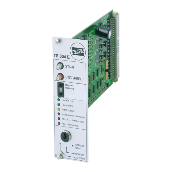
Controlling with the Electronic Control Card TS004 E 3 Technical Data 3.1 General specifications 3.2 Terminal connection 4 Description of the Inputs and Outputs 4.1 Inputs 4.2 Outputs 5 Operating Controls 6 Installation Instructions 6.1 Card holder...
Safety instructions Safety and application instructions Validity: These instructions apply to control cards in the model series: TS 002 E TS 003 E TS 004 E Symbols: Warnings are emphasised by a safety symbol and are shown as follows depending on the degree of risk: Imminent danger.
Page 5
Skin contact will cause burns. Warning! WEISS devices conform to the relevant VDE regulations. The VDE regulations must also be observed in the case of modification or extension of the devices. This documentation contains instructions for an installation in accordance with the EMC regulations. Compliance with the limit values stipulated by EMC legislation is the responsibility of the manufacturer of the system or machine.
Page 6
EMERGENCY STOP: Suitable protective devices in accordance with EN 60204 Part 1 must be used. Adequate protective devices, e.g. covers, protective grids, light curtains or step sensors must be installed for operation in order to protect the operating personnel from injury by the rotary indexing table. Danger! In the case of an EMERGENCY STOP the motor line must be reliably interrupted in order to stop the supply of energy and to ensure protection against unintentional re-starting.
Controlling with the electronic control card TS004 E We provide this electronic control card for use in controlling our cam indexing tables (TC, TR and TS). This card monitors the operation of the indexing table and also allows you to optimize the indexing time. The card provides for manual operation as well as independent contol by your main PLC.
Technical data General Specifications Operating voltage 24V DC +/- 10% Power consumption typ. 40mA (without 24 V brake) Power consumption brake 1.0 to 2.0 DC (depending on type) Digital inputs Level: LOW: 0V to 5V HIGH: 15V to 30V Input current: 6mA Digital outputs Output current: 100 mA (outputs: 4, 6, 7, 8, 9, 10) Output current: 2.0 A (outputs: C, D, E)
Description of inputs and outputs Inputs Terminal 1: Rotation direction Direction of rotation CW (right) HIGH Direction of rotation CCW (left) The signal must appear on the rising/leading edge of cam and the direction of rotation must be determined (Output “C“ or “E“). Terminal 2: Enable (RESET/Stop) It is absolutely necessary to wire this input.
Page 11
Terminal “G“: Manual mode brake A HIGH signal opens the brake. The table cannot be started Make sure that the motor line is properly disconnected to avoid hand injuries due to the motor suddenly starting up. Warning! Terminal “H“: Start status-controlled A LOW/HIGH edge starts a cycle.
Outputs: Terminal 4: Automatic This output signals HIGH when the front panel key switch is on “Automatic”. Terminal 6: Alarm: Position overrun This output signals HIGH when the indexing table has overrun the stop position. Terminal 7: Alarm: Drive time timeout (motor overload) This output signals HIGH when the indexing table has not reached the position cam approx.
Operating controls stop delay Rotary switch for stop delay table in position table rotating return short circuit/high temp. motor-/table overload position overrun Key for operating mode BRAKE release INCHING AUTOMATIC 1. START key The light (LED green) signals that there is 24 V at the control card. If the key switch is at “STEP“ (manual mode), a cycle can be triggered by pressing the START key.
Page 14
The multiplicator of this time scale is set at the rotary switch “Stop delay“ (at the front panel) between 0 and 9. = no delay 1 - 9 = delay factor in 1-9 x 20, 40 or 80 ms increments Optimum setting 1.
Installation instructions Card holder This is our recommended standard version (din rail mounting) The card holder is designed for installation fixing to din rails in rear of electrical panel. It has screw wiring terminals on the left and right hand sides for the connection of the 24V and the control wires. Terminal PCB single terminal PCB (screw fixing) The PCB terminal is designed for installation screw fixing.
Page 16
Versions: without door with door front panel mounting installation fixing onto din rails screw fastening...
Wiring Circuit diagram indexing table TC or TR terminal C electronic contactor motor line E-STOP brake sensor Motor line The motor line is switched by use of an electronic relay (solid state relay). Following this the two obligatory E-Stop contactors must be connected to ensure a reliable shutdown in the event of an E-STOP. Please see the motor name plate for the dimensioning of the motor protection switch.
- Voltage peaks > 30 V on signals - Supply voltage > 30 V High motor HIGH - Motor too hot temperature - Temperature switch interrupted For trouble shooting please contact our Head Office: WEISS GmbH Siemensstraße 17 D-74722 Buchen/Odw. Tel.: +49 (0)6281/5208-0 www.weiss-gmbh.de service@weiss-gmbh.de...
Appendix Manufacturers Declaration EC - Manufacturers Declaration according to annex II B of the EC Machine directive (98/27/EC) Manufacturer: WEISS GmbH Sondermaschinentechnik Siemensstraße 17 D-74722 Buchen Germany hereby declares that the machine described below: Control card TS004 E Is not ready for operation in the sense of the EC machinery directive and therefore does not comply entirely with the...
Need help?
Do you have a question about the TS 002 E and is the answer not in the manual?
Questions and answers