
Related Manuals for WEISS TS004E


Summary of Contents for WEISS TS004E
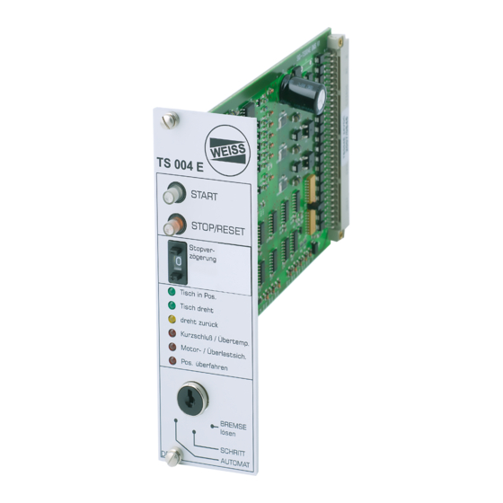
- Page 1 ELECTRONIC CONTROL CARD ELECTRONIC CONTROL CARD TS004E TS004E USER MANUAL USER MANUAL TD0080A-EN00-0000-00 TD0080A-EN00-0000-00 082018_1.0_EN 082018_1.0_EN...
-
Page 2: Table Of Contents
Electronic Control Card TS004E Table of contents Table of contents Introduction............................... 4 About this user manual......................... 4 Intended use..........................4 Predictable incorrect application....................4 Applicable documents........................5 Safety................................. 6 Safety messages and hazard categories..................6 Hazard symbols..........................6 Responsibilities of the system integrator and/or operator.............7 Qualification of personnel......................7... - Page 3 Electronic Control Card TS004E Table of contents 8.2.4 Terminal 5............................ 19 8.2.5 Terminal F............................19 8.2.6 Terminal G........................... 19 8.2.7 Terminal H........................... 20 8.2.8 Terminal T............................20 Description of the outputs......................20 8.3.1 Terminal 4............................ 20 8.3.2 Terminal 6............................ 21 8.3.3 Terminal 7............................ 21 8.3.4...
-
Page 4: Introduction
Introduction Introduction About this user manual This user manual describes the product Electronic Control Card TS004E (also referred to as "product" in this document). This user manual is a part of the product. You may only use the product if you have fully read and understood this user manual. -
Page 5: Applicable Documents
Electronic Control Card TS004E Introduction Applicable documents In addition to this user manual, the following documents are binding for and apply to any type of use of the product: Order data (including, but not limited to, design data, load data, performance data, transportation and storage instructions, information attached to the product and the package, as well as other specifications). -
Page 6: Safety
Electronic Control Card TS004E Safety Safety Safety messages and hazard categories This user manual contains safety messages to alert you to potential hazards and risks. Safety messages in this user manual are highlighted with warning symbols and warning words. The signal word describes the source of the hazard. The text contains instructions on how to avoid the hazard as well as the consequence resulting from failure to follow the instructions given in the safety message. -
Page 7: Responsibilities Of The System Integrator And/Or Operator
Electronic Control Card TS004E Safety Responsibilities of the system integrator and/or operator The system integrator (the person who incorporates the product in a machine pursuant to Directive 2006/42/EU, i.e., for example, the machine builder) and/or the operator must ensure the following: The application and use of the product must be limited to the specified intended use. -
Page 8: Function Description
Electronic Control Card TS004E Function description Function description The product is used to control and monitor the rotary indexing table types (TC) and the rotary indexing ring types (TR) with position cams. It allows for autonomous operation of the rotary indexing table/ rotary indexing ring and for control via a master controller (PLC). -
Page 9: Technical Data
Electronic Control Card TS004E Technical data Technical data Technical data "Control Cad" Characteristic Unit Value Operating voltage 24 (± 10%) Current input Typ. 40 (without 24 V holding brake) Input power holding brake 1.0 ... 2.0 (depends on type) Digital inputs Level LOW: 0 ... -
Page 10: Climatic Environmental Conditions Operation
Electronic Control Card TS004E Technical data Termi- Function Level Remark 32-pin mul- tipoint con- nector General error Output 24 V/100 mA 9A/B Start permissible Output 24 V/100 mA 8B Table in Pos./ Output 24 V/100 mA processing released Output 24 V/100 mA... -
Page 11: Dimensions
Electronic Control Card TS004E Technical data Dimensions Figure 1: Lengths in mm 11 / 29 User manual_082018_1.0_en... -
Page 12: Packaging, Transportation And Storage
Document the damage in the transportation documents/bill of delivery (any damage detected must be immediately reported to the forwarding agent and confirmed by the forwarding agent). Take photographs of the damage. Report the damage to WEISS GmbH. Packaging and shipment The product is delivered in an accurately fitting plastic packaging. -
Page 13: Storage
Electronic Control Card TS004E Packaging, transportation and storage Storage NOTICE INCORRECT STORAGE Verify compliance with all conditions specified in this user manual and all applicable documents when storing the product. Failure to follow these instructions can result in equipment damage. -
Page 14: Mounting
Electronic Control Card TS004E Mounting Mounting Mounting versions Terminal PCB Terminal PCB individually Card holder The card holder is provided for DIN rail mounting or screw mounting. The card holder has screw terminals on the left and right hand sides for the connection of the 24 V cables and the signal cables. -
Page 15: Wiring
Electronic Control Card TS004E Wiring Wiring Block diagram Electronic control card TS004E Terminal F 24 V inputs and outputs Terminal D 3 x 400 V Motor cable Rotary indexing table/rotary indexing ring TC/TR 10 Emergency Stop Terminal C Holding brake... -
Page 16: Commissioning
Electronic Control Card TS004E Commissioning Commissioning Prior to switching on the product, verify that the motor housing is correctly connected to ground potential (PE busbar). DANGER ELECTRIC SHOCK CAUSED BY LIVE PARTS Control connections and power connection can carry voltage even if the motor is at a standstill. - Page 17 Electronic Control Card TS004E Commissioning 3 Counter indicator stop delay As soon as the locked phase is reached, the position signal is avail- able at terminal 10, but the stop signal for the drive is not yet active. This signal is triggered with a delay so that the rotary indexing ta- ble/rotary indexing ring is stopped at the end of the locked phase.
-
Page 18: Description Of The Inputs
Electronic Control Card TS004E Commissioning 4 Status indicators table in position The LED lights green if the rotary indexing table/rotary indexing ring is in position, i.e. the output flange is locked The LED lights solid green as long as the... -
Page 19: Terminal 3
Electronic Control Card TS004E Commissioning The signal must be available with a rising edge of the start signal; it determines the direction of rotation (outputs C and E). 8.2.2 Terminal 2 Enable (RESET/STOP) This input must be wired. -Disable (motor STOP) -
Page 20: Terminal H
Electronic Control Card TS004E Commissioning 8.2.7 Terminal H Start state-controlled A LOW/HIGH edge starts a cycle. As opposed to input 3 the level at this input must be HIGH during the entire movement. If the level changes to LOW, the rotary indexing table/rotary indexing ring immediately stops (in an intermediate position). -
Page 21: Terminal 6
Electronic Control Card TS004E Commissioning 8.3.2 Terminal 6 Error: Position overtraveled The level at this output is HIGH if the rotary indexing table/rotary indexing ring has overtraveled the locked position. 8.3.3 Terminal 7 Error: Motor overload (movement timeout) The level at this output is HIGH if the rotary indexing table/rotary indexing ring has not reached the inductive sensor approximately 10 seconds after the start signal. -
Page 22: Operation
Electronic Control Card TS004E Operation Operation Normal operation (one direction of rotation) 22 / 29 User manual_082018_1.0_en... -
Page 23: Forward/Reverse Operation (Two Directions Of Rotation)
Electronic Control Card TS004E Operation Forward/reverse operation (two directions of rotation) 23 / 29 User manual_082018_1.0_en... -
Page 24: Errors
Electronic Control Card TS004E Errors Errors 10.1 Troubleshooting and error messages Troubleshooting In the case of an error, the red LED lights solid in the button STOP/RESET. The outputs 6, 7, 8 signal the error. The error message can be reset with the button STOP/RESET or with a LOW signal at terminal 2. -
Page 25: Disposal
Electronic Control Card TS004E Disposal Disposal 11.1 Disposing of the product Dispose of the product in compliance with all applicable directives, standards, and safety regulations. Environmental protection Dispose of lubricants, greases, residue of cleaning agents and other non-recyclable materials according to the applicable directives, standards, and safety regulations. -
Page 26: Service And Spare Parts
Fax +31-84-7118833 E-mail info@weiss-gmbh.de E-Mail info@weiss-gmbh.ch E-mail info@weiss-gmbh.nl POLAND ITALY USA | CANADA WEISS Poland Sp. z o. o. WEISS Italia S.r.l. WEISS North America, Inc. ul. Wielicka 250 Via dell'Arcoveggio 49/5 3860 Ben Hur Avenue, Suite 3 30-663 Kraków... -
Page 27: Service
Electronic Control Card TS004E Service and spare parts 12.2 Service If you need the assistance of our service departments, please provide the following information: Serial number of the product (see label on frame connector) Description of the problem Time of occurrence and circumstances of the problem Suspected cause You can reach our service department from Monday to Friday 08:00 a.m to 05:00 p.m. -
Page 28: Spare Parts
Electronic Control Card TS004E Service and spare parts 12.4 Spare parts Part number Designation Description Quantity EK0004D-1000-0000-00 Electronic control card Control card with German label TS004E EK0004E-1000-0000-00 Electronic control card Control card with English label TS004E EK0004F-1000-0000-00 Electronic control card... - Page 29 WEISS GmbH Siemensstraße 17 74722 Buchen Telefon 06281 5208-0 Telefax 06281 5208-99 info@weiss-international.com www.weiss-international.com...
Need help?
Do you have a question about the TS004E and is the answer not in the manual?
Questions and answers