
Subscribe to Our Youtube Channel
Related Manuals for WEISS EF2 Series


Summary of Contents for WEISS EF2 Series
- Page 1 ROTARY INDEXING TABLE CONTROLER MANUAL ELECTRICAL SYSTEM DOCUMENTATION EN_06_2016...
- Page 2 All rights in this document are the copyright of WEISS GmbH. This document may not be copied or reproduced, in whole or in part, without the written permission of WEISS GmbH. This document is only intended for the user of the...
-
Page 3: Table Of Contents
ROTARY INDEXING TABLE CONTROLLER EF2...B TABLE OF CONTENTS INTRODUCTION ............................. 7 Definition ..............................7 Intended use ............................7 Target group ............................7 Controller components ........................... 8 Further applicable documents ......................11 Manual ..............................11 1.6.1 Validity ..............................11 1.6.2 Standard scope ............................ 11 1.6.3 Explanation of safety instructions in this manual ................. - Page 4 ROTARY INDEXING TABLE CONTROLLER EF2...B Time sequence diagrams ........................39 4.4.1 Example for time sequence diagram of the signal "Start cycle CW" ............ 39 4.4.2 Example for time sequence diagram of the signal "Start level CW" ............ 40 Interface assignment D410-2 ....................... 41 4.5.1 Interface X120 .............................
- Page 5 ROTARY INDEXING TABLE CONTROLLER EF2...B OPERATION / DESCRIPTION OF WEISS SOFTWARE ................76 Start page ............................77 8.1.1 User interface on the start page ......................78 8.1.2 Login ..............................79 Overview .............................. 80 Machine configuration .......................... 81 8.3.1 Ethernet interface ..........................81 8.3.2 Reset factory settings ..........................
- Page 6 ROTARY INDEXING TABLE CONTROLLER EF2...B DIAGNOSTICS ............................139 11.1 Messages ............................139 11.2 Error and state indicators ........................140 11.3 Error messages ..........................141 STANDARDS AND APPROVALS ......................149 12.1 CE marking ............................149 12.2 Electromagnetic compatibility ......................149 12.3 cULus approval ..........................150 APPENDIX ..............................
-
Page 7: Introduction
The controller is optimally designed for operation with the TC and TR rotary indexing tables and offers you the follo- wing benefits: • Optimally tuned frequency converter control for electro-mechanical WEISS rotary indexing tables • Intuitive, web-based user interface for fast commissioning •... -
Page 8: Controller Components
ROTARY INDEXING TABLE CONTROLLER EF2...B INTRODUCTION | 1.4 Controller components Controller components Fig. 1: Controller components The components of the controller are delivered as individual modules. Their assembly and wiring are the responsibi- lity of the user. Pos. Component Type / Characteristics Control unit SIMOTION D410-2 Power module... - Page 9 ROTARY INDEXING TABLE CONTROLLER EF2...B INTRODUCTION | 1.4 Controller components PM240-2 FSA 24 VDC Fieldbus (Profibus / Profinet) PM-IF Digital I/O Ethernet Safe Brake Relay 24 VDC Fig. 2: Block diagram of EF2...B controller with PM240-2 FSA Manual R06-2016 9 / 172...
- Page 10 ROTARY INDEXING TABLE CONTROLLER EF2...B INTRODUCTION | 1.4 Controller components PM240-2 FSB 24 VDC Fieldbus (Profibus / Profinet) PM-IF Digital I/O Ethernet Safe Brake Relay 24 VDC Fig. 3: Block diagram of EF2...B controller with PM240-2 FSB 10 / 172 Manual R06-2016...
-
Page 11: Further Applicable Documents
ROTARY INDEXING TABLE CONTROLLER EF2...B INTRODUCTION | 1.5 Further applicable documents Further applicable documents In addition to this manual, further documents are required for installation of the controller and safe operation of a machine with this controller. Compliance with the information in these documents must be regarded. ... -
Page 12: Explanation Of Safety Instructions In This Manual
ROTARY INDEXING TABLE CONTROLLER EF2...B INTRODUCTION | 1.6 Manual 1.6.3 Explanation of safety instructions in this manual This manual contains instructions that you should observe for your personal safety and to avoid material damage. Safety instructions for your personal safety are highlighted by a sign containing a warning triangle and signal word. The associated text describes the hazard involved, avoidance options and the consequences which may result from failure to observe the safety instructions. -
Page 13: Safety
ROTARY INDEXING TABLE CONTROLLER EF2...B SAFETY | 2.1 Basic safety instructions SAFETY Basic safety instructions The controller corresponds to the state of the art and the applicable stipulations of the VDE. It provides a high level of safety. This safety can only be achieved during actual operation, however, when all associated necessary measures have been performed. -
Page 14: Technical Safety
ROTARY INDEXING TABLE CONTROLLER EF2...B SAFETY | 2.1 Basic safety instructions 2.1.2 Technical safety WARNING During operation, electrical equipment and motors have parts and components with hazardous voltage levels, which touched, can cause severe bodily injury or death. All work on the electrical system must be carried out when the system has been disconnected from the power supply (de-energized). -
Page 15: Electrostatic Safety
ROTARY INDEXING TABLE CONTROLLER EF2...B SAFETY | 2.2 Emergency Stop Circuit 2.1.3 Electrostatic safety NOTICE Electrostatic sensitive devices (ESDs) are individual components, integrated circuits, or modules that may be dama- ged by either electrostatic fields or electrostatic discharge. Regulations for handling ESD components: When handling electronic components, make sure that personnel, workstations, and pakkaging are well grounded! Personnel may only come into contact with electronic components, if •... -
Page 16: Residual Hazards
ROTARY INDEXING TABLE CONTROLLER EF2...B SAFETY | 2.3 Residual hazards Residual hazards When carrying out a risk assessment of a machine in accordance with the EC Machinery Directive, the machine manufacturer must consider the following residual risks which originate at the components of the controller and the drive: •... - Page 17 ROTARY INDEXING TABLE CONTROLLER EF2...B SAFETY | 2.3 Residual hazards WARNING Electric shock Power and control connections can still conduct electricity even if the machine is at a standstill. Work on electrical equipment should only be performed by qualified electricians in compliance with the instructions in the operating manual for the electrical system documentation.
-
Page 18: Component Descriptions
ROTARY INDEXING TABLE CONTROLLER EF2...B COMPONENT DESCRIPTIONS | 3.1 Power Modules PM240-2 COMPONENT DESCRIPTIONS Power Modules PM240-2 The power modules are designed as follows: • Mains-side diode rectifier • DC-link electrolytic capacitors with pre-charging circuit • Output inverter IGBT • Braking chopper for (external) braking resistor •... -
Page 19: Power Module Pm240-2; Frame Size Fsa
ROTARY INDEXING TABLE CONTROLLER EF2...B COMPONENT DESCRIPTIONS | 3.1 Power Modules PM240-2 3.1.2 Power Module PM240-2; frame size FSA Fig. 4: Interfaces of Power Module PM240-2; frame size FSA The connections for mains, brake resistor and motor are detachable plug connections and are located on the bottom side of the power module. -
Page 20: Power Module Pm240-2; Frame Size Fsb
ROTARY INDEXING TABLE CONTROLLER EF2...B COMPONENT DESCRIPTIONS | 3.1 Power Modules PM240-2 3.1.3 Power Module PM240-2; frame size FSB Fig. 5: Interfaces of Power Module PM240-2; frame size FSB The connections for mains, brake resistor and motor are detachable plug connections and are located on the bottom side of the power module. -
Page 21: Technical Data
ROTARY INDEXING TABLE CONTROLLER EF2...B COMPONENT DESCRIPTIONS | 3.1 Power Modules PM240-2 3.1.4 Technical data Standard Power Modules PM240-2 • 6SL3210- 6SL3210- 6SL3210- 6SL3210- Without integrated line filter 1PB13-0UL0 1PE16-1UL1 1PE18-0UL1 1PE21-1UL0 • 6SL3210- 6SL3210- 6SL3210- 6SL3210- With integrated line filter 1PB13-0AL0 1PE16-1AL1 1PE18-0AL1... - Page 22 ROTARY INDEXING TABLE CONTROLLER EF2...B COMPONENT DESCRIPTIONS | 3.1 Power Modules PM240-2 Standard Power Modules PM240-2 • 6SL3210- 6SL3210- 6SL3210- 6SL3210- Without integrated line filter 1PB13-0UL0 1PE16-1UL1 1PE18-0UL1 1PE21-1UL0 • 6SL3210- 6SL3210- 6SL3210- 6SL3210- With integrated line filter 1PB13-0AL0 1PE16-1AL1 1PE18-0AL1 1PE21-1AL0 Dimensions...
-
Page 23: Overview Power Module Pm240-2
ROTARY INDEXING TABLE CONTROLLER EF2...B COMPONENT DESCRIPTIONS | 3.1 Power Modules PM240-2 3.1.5 Overview Power Module PM240-2 3 AC 380 V ... 480 V 1 AC 200 V ... 240 V L1L2 L3 PE Fuses Fuses OPTION: OPTION: OPTION: OPTION: Power choke Power choke Power choke... -
Page 24: External Braking Resistor (Option)
ROTARY INDEXING TABLE CONTROLLER EF2...B COMPONENT DESCRIPTIONS | 3.2 External braking resistor (option) External braking resistor (option) The Power Modules PM240-2 are assigned to fixed values of the braking resistors: 0.37 kW, 1 AC 230 V, 390 ohm, peak power = 1.5 kW 1.50 kW, 3 AC 400 V, 150 ohm, peak power = 2.75 kW 2.20 kW, 3 AC 400 V, 150 ohm, peak power = 2.75 kW 3.00 kW, 3 AC 400 V, 80 ohm, peak power = 4.0 kW... -
Page 25: Motor Contactor
ROTARY INDEXING TABLE CONTROLLER EF2...B COMPONENT DESCRIPTIONS | 3.3 Motor contactor Motor contactor A power contactor can be used as a switching device for switching the motor to comply with safety requirements according to SIL3. In combination with a safety relay (see chapter 3.4), the requirements can be met for a safety integrity level SIL3 or performance level PLe to their fullest extent, depending on the external circuit. -
Page 26: Safety Relay
ROTARY INDEXING TABLE CONTROLLER EF2...B COMPONENT DESCRIPTIONS | 3.4 Safety relay Safety relay Type 3SK1122-1CB41 The safety relay 3SK1122 features two safety-related semi-conductor outputs and a non-safety-related semi-con- ductor signalling circuit. The front of the device features a 4-way DIP switch for function configuration and 4 LEDs for status and function indication. -
Page 27: Technical Data
ROTARY INDEXING TABLE CONTROLLER EF2...B COMPONENT DESCRIPTIONS | 3.4 Safety relay Fig. 10: Circuit safety relay 3.4.1 Technical data Safety relay Sirius 3SK1122-1CB41 Version for emergency stop and protection doors Degree of protection IP20 Contact protection against electric shock finger-safe Ambient temperature Storage -40 °C...+80 °C... -
Page 28: Terminal Module Tm15
ROTARY INDEXING TABLE CONTROLLER EF2...B COMPONENT DESCRIPTIONS | 3.5 Terminal Module TM15 Terminal Module TM15 The Terminal Module provides 24 DI/DO (digital I/Os). In the case of EF2, the digital inputs and outputs are permanently assigned as 12 DI and 12 DO. The TM15 terminal module is connected to the SIMOTION D410-2 via DRIVE-CLiQ. -
Page 29: Brake Relay
ROTARY INDEXING TABLE CONTROLLER EF2...B COMPONENT DESCRIPTIONS | 3.6 Brake Relay Brake Relay A Brake Relay is required for operating motors with holding brakes up to 2 A (included in the scope of delivery). The Brake Relay is the interface between the CU / Power Modules Blocksize and the 24 V DC motor brake. The motor brake is electronically controlled. -
Page 30: Brake Relay Connection Example
ROTARY INDEXING TABLE CONTROLLER EF2...B COMPONENT DESCRIPTIONS | 3.6 Brake Relay 3.6.2 Brake Relay connection example Brake Relay Fig. 13: Brake Relay connection example 30 / 172 Manual R06-2016... -
Page 31: Simotion D410-2 Control Unit
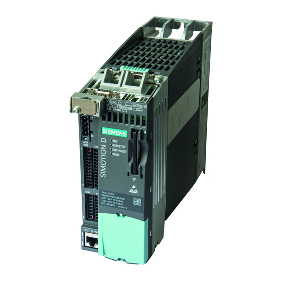
ROTARY INDEXING TABLE CONTROLLER EF2...B COMPONENT DESCRIPTIONS | 3.7 SIMOTION D410-2 Control Unit SIMOTION D410-2 Control Unit SIMOTION D is the drive-based version of SIMOTION based on the SINAMICS S120 drive family. In SIMOTION D, the SIMOTION PLC and motion control functionalities as well as the SINAMICS S120 drive soft- ware run on shared control hardware. -
Page 32: Technical Data
ROTARY INDEXING TABLE CONTROLLER EF2...B COMPONENT DESCRIPTIONS | 3.7 SIMOTION D410-2 Control Unit Pos. Description LED status indicators CF card slot Type plate Pos. Interface Description PM-IF Interface to the power module (on the rear) Encoder interface X100 DRIVE-CLIQ interface X150 PROFINET IO interfaces PROFIBUS DP interface... -
Page 33: Mac Addresses
3.7.3 CompactFlash Card The CompactFlash card is mandatory for operation of the SIMOTION D410-2. The SIMOTION Kernel (SIMOTION D410-2 firmware) and the software used to control the drives (WEISS firmware) are stored on the CompactFlash card. Manual R06-2016 33 / 172... -
Page 34: Function And Signal Descriptions
ROTARY INDEXING TABLE CONTROLLER EF2...B FUNCTION AND SIGNAL DESCRIPTIONS | 4.1 Signal description of the software inputs FUNCTION AND SIGNAL DESCRIPTIONS Signal description of the software inputs Default configuration Signal Function Inputs PED 256 The output stage of the controller is enabled if the signal level is HIGH. The output stage of the controller is disabled if the signal level is LOW. - Page 35 ROTARY INDEXING TABLE CONTROLLER EF2...B FUNCTION AND SIGNAL DESCRIPTIONS | 4.1 Signal description of the software inputs Default configuration Signal Function Inputs PED 256 Parameter set 3 is used for starting from an intermediate position. Only if the position cam of the rotary indexing table has not been activa- ted and a start is executed.
-
Page 36: Signal Description Of The Software Outputs
ROTARY INDEXING TABLE CONTROLLER EF2...B FUNCTION AND SIGNAL DESCRIPTIONS | 4.2 Signal description of the software outputs Signal description of the software outputs Default configuration Signal Function Outputs PAD 256 Ready for All conditions are fulfilled. The release of the drive can be given via the Bit 12 switching on Enable input. - Page 37 ROTARY INDEXING TABLE CONTROLLER EF2...B FUNCTION AND SIGNAL DESCRIPTIONS | 4.2 Signal description of the software outputs Default configuration Signal Function Outputs PAD 256 The watchdog mechanism serves to monitor the life sign of the EF2 by the superordinate controller. A signal can be specified by the superordinate controller via "Receive watchdog".
-
Page 38: Functions And Signals Tm15
ROTARY INDEXING TABLE CONTROLLER EF2...B FUNCTION AND SIGNAL DESCRIPTIONS | 4.3 Functions and signals TM15 Functions and signals TM15 4.3.1 Terminal Module TM15 connection example + 24 DC + 24 DC + 24 DC + 24 DC -X501 -X501 DRIVE-CLIQ DRIVE-CLIQ -X500 -X500... -
Page 39: Time Sequence Diagrams
ROTARY INDEXING TABLE CONTROLLER EF2...B FUNCTION AND SIGNAL DESCRIPTIONS | 4.4 Time sequence diagrams Time sequence diagrams 4.4.1 Example for time sequence diagram of the signal "Start cycle CW" The same is also valid for the signal "Start cycle CCW". (I) Enable (I) Stop (low active) (I) Start cycle CW... -
Page 40: Example For Time Sequence Diagram Of The Signal "Start Level Cw
ROTARY INDEXING TABLE CONTROLLER EF2...B FUNCTION AND SIGNAL DESCRIPTIONS | 4.4 Time sequence diagrams 4.4.2 Example for time sequence diagram of the signal "Start level CW" The same is also valid for the signal "Start level CCW". (I) Enable (I) Stop (low active) (I) Start level CW (O) Ready for... -
Page 41: Interface Assignment D410-2
ROTARY INDEXING TABLE CONTROLLER EF2...B FUNCTION AND SIGNAL DESCRIPTIONS | 4.5 Interface assignment D410-2 Interface assignment D410-2 4.5.1 Interface X120 Electric shock Only temperature sensors that meet the safety isolation specifications specified in EN 61800-5-1 may be connected to terminals "+Temp" and "-Temp". If safe electrical separation cannot be guaranteed (for linear motors or third-party motors, for example), a Sensor Module External (SME120 or SME125) or Terminal Module TM120 must be used. -
Page 42: Interface X121
ROTARY INDEXING TABLE CONTROLLER EF2...B FUNCTION AND SIGNAL DESCRIPTIONS | 4.5 Interface assignment D410-2 4.5.2 Interface X121 Representation Name Description DI 0 Motor temperature switch DI 1 HW limit switch CW (low active) DI 2 HW limit switch CCW (low active) DI 3 Motor contactor feedback Ground reference for DI 0 …... -
Page 43: Interface X127
ROTARY INDEXING TABLE CONTROLLER EF2...B FUNCTION AND SIGNAL DESCRIPTIONS | 4.5 Interface assignment D410-2 4.5.4 Interface X127 Interface X127 serves as the service interface. This interface (Web interface) is used to configure the rotary indexing table. 4.5.5 Interface X130 This interface is not used in the standard version! Representation Name... -
Page 44: Interface X131
ROTARY INDEXING TABLE CONTROLLER EF2...B FUNCTION AND SIGNAL DESCRIPTIONS | 4.5 Interface assignment D410-2 4.5.6 Interface X131 Representation Name Description DI/DO 12 Feedback 24-V power supply of brake relay DI/DO 13 Do not use Do not use DI/DO 14 Do not use DI/DO 15 Do not use Do not use... -
Page 45: Interface Assignment Tm15
ROTARY INDEXING TABLE CONTROLLER EF2...B FUNCTION AND SIGNAL DESCRIPTIONS | 4.6 Interface assignment TM15 Interface assignment TM15 The Terminal Module provides 24 DI/DO (digital I/Os). In the case of EF2, the digital inputs and outputs are permanently assigned as 12 DI and 12 DO. 4.6.1 Interface X520 Representation Terminal... -
Page 46: Interface X522
ROTARY INDEXING TABLE CONTROLLER EF2...B FUNCTION AND SIGNAL DESCRIPTIONS | 4.6 Interface assignment TM15 4.6.3 Interface X522 Representation Terminal Name DO 4 DO 5 DO 6 DO 7 DO 8 DO 9 DO 10 DO 11 M3 (GND) Screw terminal Max. -
Page 47: Safety Functions
ROTARY INDEXING TABLE CONTROLLER EF2...B SAFETY FUNCTIONS | 5.1 Integrated safety functions (SIL2) SAFETY FUNCTIONS Integrated safety functions (SIL2) The integrated safety functions of the SINAMICS S120 devices satisfy the requirements of the standard IEC 61508 SIL 2, as well as PL d acc. to ISO 13849-1 and Category 3 acc. to ISO 12849-1 or EN 954-1. The following integrated safety functions are currently provided by the SINAMICS S120 drive system: •... - Page 48 ROTARY INDEXING TABLE CONTROLLER EF2...B SAFETY FUNCTIONS | 5.2 Extended safety functions (SIL3) Fig. 19: SET screen: Calculation for FC Fig. 20: SET screen: Calculation for motor contactor 48 / 172 Manual R06-2016...
- Page 49 ROTARY INDEXING TABLE CONTROLLER EF2...B SAFETY FUNCTIONS | 5.2 Extended safety functions (SIL3) The PFHD value of the combination of the SINAMICS S120 drive including the Safety Relay 3SK1122-1CB41 and the selected Motor Contactor 3R2017-1BB42 is 1.63 E-08 in accordance with IEC62061. A sensor can be added to the safety function, a light curtain for example.
- Page 50 ROTARY INDEXING TABLE CONTROLLER EF2...B SAFETY FUNCTIONS | 5.2 Extended safety functions (SIL3) Forced dynamization: The forced dynamisation needs to be carried out every 8 hours. The forced dynamization of the shutdown paths serves the purpose of detecting errors on time that occur in the soft- ware and hardware of the two monitoring channels of the integrated safety functions of the SINAMICS S120.
-
Page 51: Installation
ROTARY INDEXING TABLE CONTROLLER EF2...B INSTALLATION | 6.1 External braking resistor (option) INSTALLATION External braking resistor (option) The PM240-2 Power Modules cannot recover generated power and feed it back into the grid. For operations which produce energy, e.g. braking of a rotating mass, a braking resistor must be connected to con- vert the generated power into heat. - Page 52 ROTARY INDEXING TABLE CONTROLLER EF2...B INSTALLATION | 6.1 External braking resistor (option) View with premounted DIN rail clamping brackets 13,85 62,3 Temperature switch up to 200°C View with premounted screws to fix the frequency inverter with hole pattern 186/62.3 Fig. 23: Dimensions BWD500 52 / 172 Manual R06-2016...
- Page 53 ROTARY INDEXING TABLE CONTROLLER EF2...B INSTALLATION | 6.1 External braking resistor (option) View with premounted DIN rail clamping brackets Temperature switch up to 200°C View with premounted screws to fix the frequency inverter with hole pattern Fig. 24: Dimensions BWD600 Manual R06-2016 53 / 172...
-
Page 54: Mounting / Connecting The Braking Resistor
ROTARY INDEXING TABLE CONTROLLER EF2...B INSTALLATION | 6.1 External braking resistor (option) 6.1.2 Mounting / Connecting the braking resistor 1. Drill boreholes in the control cabinet depending on the dimensions of the brake resistor used (see chapter 6.1.1 „Dimensions, hole patterns“ on page 51). 2. -
Page 55: Power Module Pm240-2; Frame Size Fsa / Fsb
ROTARY INDEXING TABLE CONTROLLER EF2...B INSTALLATION | 6.2 Power Module PM240-2; frame size FSA / FSB Power Module PM240-2; frame size FSA / FSB The following is necessary for a proper assembly of the power module: • Mount the power module in a control cabinet. ... -
Page 56: Dimensions, Hole Patterns
Take the boreholes for brake resistor and shielding plate into account Power module, brake resistor and shielding plate have different hole patterns. WEISS GmbH recommends drilling the boreholes for all three components during the installation. This way, further drilling, possible interferences due to metal chips and mechanical loads are avoided during an eventual retrofitting. -
Page 57: Frame Size Ef2300
Take the boreholes for brake resistor and shielding plate into account Power module, brake resistor and shielding plate have different hole patterns. WEISS GmbH recommends drilling the boreholes for all three components during the installation. This way, further drilling, possible interferences due to metal chips and mechanical loads are avoided during an eventual retrofitting. -
Page 58: Mounting The Shielding Plate
ROTARY INDEXING TABLE CONTROLLER EF2...B INSTALLATION | 6.2 Power Module PM240-2; frame size FSA / FSB 6.2.2 Mounting the shielding plate The shielding plate and the fastening screws are included in the accessory bag of the convertor. Shielding plate and safe brake relay have already been factory-fitted. Fig. -
Page 59: Mounting / Connecting The Power Module
1. Drill boreholes in the control cabinet depending on the dimensions of the power module used (see chapter 6.2.1 „Dimensions, hole patterns“ on page 56). 2. Drill boreholes for the brake resistor and the shielding plate according to the recommendation of WEISS GmbH. 3. Regard the required cooling and mounting clearances. -
Page 60: Emc-Compliant Installation
ROTARY INDEXING TABLE CONTROLLER EF2...B INSTALLATION | 6.2 Power Module PM240-2; frame size FSA / FSB 6.2.4 EMC-compliant installation Rules for an EMC-compliant cable routing: • Mount the power module on a metal mounting plate. The mounting plate has to be uncoated and electrically well conductive. -
Page 61: Power Mains Connection 1 Ac 200 V - 240 V / 0.37 Kw
ROTARY INDEXING TABLE CONTROLLER EF2...B INSTALLATION | 6.2 Power Module PM240-2; frame size FSA / FSB 6.2.4.1 Power mains connection 1 AC 200 V - 240 V / 0.37 kW Cyclical switching of the supply voltage is not allowed. After each shutdown, wait five minutes before switching it on again. -
Page 62: Power Mains Connection 3 Ac 380 V - 480 V / 1.5 Kw
ROTARY INDEXING TABLE CONTROLLER EF2...B INSTALLATION | 6.2 Power Module PM240-2; frame size FSA / FSB 6.2.4.2 Power mains connection 3 AC 380 V - 480 V / 1.5 kW Cyclical switching of the supply voltage is not allowed. After each shutdown, wait five minutes before switching it on again. -
Page 63: Power Mains Connection 3Ac 380 V - 480 V / 2.2 - 3.0 Kw
ROTARY INDEXING TABLE CONTROLLER EF2...B INSTALLATION | 6.2 Power Module PM240-2; frame size FSA / FSB 6.2.4.3 Power mains connection 3AC 380 V - 480 V / 2.2 - 3.0 kW Cyclical switching of the supply voltage is not allowed. After each shutdown, wait five minutes before switching it on again. -
Page 64: Connecting The Motor
ROTARY INDEXING TABLE CONTROLLER EF2...B INSTALLATION | 6.2 Power Module PM240-2; frame size FSA / FSB 6.2.5 Connecting the motor Electric shock Cable shields and unused conductors of power cables (e.g. brake conductors) must be connected to PE potential to prevent capacitive cross-coupling charges. -
Page 65: Permissible Motors
ROTARY INDEXING TABLE CONTROLLER EF2...B INSTALLATION | 6.2 Power Module PM240-2; frame size FSA / FSB 6.2.5.1 Permissible motors Motors should be used for converter operation or with greater isolation. • Motors for 200-V-Power Modules Asynchronous motor in the range of 25 % … 150 % of the converter output are permissible without restrictions for 200-V-Power Modules. -
Page 66: Motor Connection Pm240-2, Frame Size Fsb
ROTARY INDEXING TABLE CONTROLLER EF2...B INSTALLATION | 6.2 Power Module PM240-2; frame size FSA / FSB 6.2.5.3 Motor connection PM240-2, frame size FSB The plug connections are located on the bottom side of the power module. Name Motor connection plug Release lever Motor phase U Motor phase V... -
Page 67: Brake Relay
ROTARY INDEXING TABLE CONTROLLER EF2...B INSTALLATION | 6.3 Brake Relay Brake Relay 6.3.1 Mounting the brake relay The safe brake relay is mounted on the rear of the bottom shielding plate of the power module. Frame size FSA Frame size FSB Fig. -
Page 68: Safety Relay
ROTARY INDEXING TABLE CONTROLLER EF2...B INSTALLATION | 6.4 Safety relay Safety relay 6.4.1 Mounting Safety Relay 3SK1122-1CB41 Fig. 40: Mounting Safety Relay 3SK1122-1CB41 The safety relay is designed to be mounted on a DIN rail. 1. Latch the safety relay onto a DIN rail. 2. -
Page 69: Terminal Module Tm15
ROTARY INDEXING TABLE CONTROLLER EF2...B INSTALLATION | 6.5 Terminal Module TM15 Terminal Module TM15 6.5.1 Mounting Terminal Module TM15 Fig. 41: Mounting Terminal Module TM15 The Terminal Module TM15 is designed to be mounted on a DIN rail. 1. Mount the Terminal Module TM15 on to a DIN rail. 2. -
Page 70: Simotion D410-2 Control Unit
ROTARY INDEXING TABLE CONTROLLER EF2...B INSTALLATION | 6.6 SIMOTION D410-2 Control Unit SIMOTION D410-2 Control Unit 6.6.1 Mounting the control unit Mounting the control unit: Fig. 42: Mechanical assembly of Control Unit D410-2 The SIMOTION D410-2 Control Unit is mounted directly on to the Power Module PM240-2. 1. -
Page 71: Inserting The Cf Card
The CF card is mandatory for operation of the SIMOTION D410-2. The SIMOTION Kernel (SIMOTION D firmware) and the software used to control the drives (WEISS firmware) are stored on the CF card. The CF card always has to be plugged in for operation. -
Page 72: Creating A Shield Connection
ROTARY INDEXING TABLE CONTROLLER EF2...B INSTALLATION | 6.6 SIMOTION D410-2 Control Unit 6.6.3 Creating a shield connection Using shielded cables The following options are available for the shield connection when using shielded cables: • A shield connection using a separately attachable shielding bus •... -
Page 73: Ef2 - Pc Connection
ROTARY INDEXING TABLE CONTROLLER EF2...B EF2 - PC CONNECTION | 7.1 Presettings EF2 - PC CONNECTION The connection of the EF2 Controller to a PC or Notebook is established using a network cable. X127 (LAN) Fig. 46: PC - EF2 Controller connection Presettings 1. - Page 74 ROTARY INDEXING TABLE CONTROLLER EF2...B EF2 - PC CONNECTION | 7.1 Presettings 2. Go to CONTROL PANEL \ NETWORK AND SHARING CENTER \ CHANGE ADAPTER SETTINGS \ LAN CON- NECTION \ PROPERTIES and make the following settings: Clear (if selected) the check box in front of Internet Protocol Version 6 (TCP/IPv6). ...
-
Page 75: Ethernet Communication Via Tcp/Ip (Via Switch)
ROTARY INDEXING TABLE CONTROLLER EF2...B EF2 - PC CONNECTION | 7.2 Ethernet communication via TCP/IP (via switch) Ethernet communication via TCP/IP (via switch) The SIMOTION D410-2 DP/PN has an onboard IE interface which is called X127 (SS-IE). This interface has an IP address and communicates via TCP/IP. -
Page 76: Operation / Description Of Weiss Software
ROTARY INDEXING TABLE CONTROLLER EF2...B OPERATION / DESCRIPTION OF WEISS SOFTWARE | 7.2 Ethernet communication via TCP/IP (via switch) OPERATION / DESCRIPTION OF WEISS SOFTWARE The Web browser of the PC or Notebook can be used to access the EF2 controller. -
Page 77: Start Page
ROTARY INDEXING TABLE CONTROLLER EF2...B OPERATION / DESCRIPTION OF WEISS SOFTWARE | 8.1 Start page Start page Fig. 50: Start page of the EF2 controller The Start page is divided into four areas: The status indicator area on the Start page shows the status of the controller and the state of the rotary indexing table. -
Page 78: User Interface On The Start Page
ROTARY INDEXING TABLE CONTROLLER EF2...B OPERATION / DESCRIPTION OF WEISS SOFTWARE | 8.1 Start page 8.1.1 User interface on the start page Fig. 51: Description of the user interface of the EF2 controller [A] Status indicator [B] Login [C] Navigation... -
Page 79: Login
ROTARY INDEXING TABLE CONTROLLER EF2...B OPERATION / DESCRIPTION OF WEISS SOFTWARE | 8.1 Start page Area Topic Section Navigation Overview Operating state of the controller (see chapter 8.2) Configured indexer type Communication Data Optional modules ... -
Page 80: Overview
ROTARY INDEXING TABLE CONTROLLER EF2...B OPERATION / DESCRIPTION OF WEISS SOFTWARE | 8.2 Overview Overview Fig. 52: Description of the "Overview" page The "Overview" page provides an overview of the current status of the rotary indexing table, as well as the configu- ration and the system data. -
Page 81: Machine Configuration
ROTARY INDEXING TABLE CONTROLLER EF2...B OPERATION / DESCRIPTION OF WEISS SOFTWARE | 8.3 Machine configuration Machine configuration 8.3.1 Ethernet interface Before beginning with the machine configuration, the Ethernet interface should be chekked. If necessary, the settings can be changed. -
Page 82: Reset Factory Settings
(chapter 8.1.2 „Login“ on page 79). 8.3.2 Reset factory settings When upgrading the WEISS firmware, the factory settings always need to be reset before starting the configuration. If an internal firmware update should be carried out by the controller afterwards, the controller has to be switched off once more before starting the configuration and then switched back on again. -
Page 83: Configuration Diagram
ROTARY INDEXING TABLE CONTROLLER EF2...B OPERATION / DESCRIPTION OF WEISS SOFTWARE | 8.3 Machine configuration 8.3.3 Configuration diagram The following configuration diagram shows all possible configurations. Follow the paths and branches of the diagram. Machine configuration [Start table configuration]... -
Page 84: Indexer Configuration
ROTARY INDEXING TABLE CONTROLLER EF2...B OPERATION / DESCRIPTION OF WEISS SOFTWARE | 8.3 Machine configuration 8.3.4 Indexer configuration 1st section of a machine configuration: Indexer configuration. There are two different ways to configure a rotary indexing table. [A] Start indexer configuration (chapter 8.3.4.1 „Start indexer configuration“ on page 84) [B] Indexer configuration via file (chapter 8.3.4.2 „Indexer configuration via file“... - Page 85 ROTARY INDEXING TABLE CONTROLLER EF2...B OPERATION / DESCRIPTION OF WEISS SOFTWARE | 8.3 Machine configuration 3. Select the type of indexer. 4. Select motor. 5. Select basic options. 6. Select extended options. 7. Input the supply voltage. The supply voltage of the power module must be input manually in the respective field.
-
Page 86: Indexer Configuration Via File
ROTARY INDEXING TABLE CONTROLLER EF2...B OPERATION / DESCRIPTION OF WEISS SOFTWARE | 8.3 Machine configuration 8.3.4.2 Indexer configuration via file "Indexer configuration via file" is not possible during initial startup because no configuration file has been stored yet. 1. Start "Indexer configuration via file". - Page 87 ROTARY INDEXING TABLE CONTROLLER EF2...B OPERATION / DESCRIPTION OF WEISS SOFTWARE | 8.3 Machine configuration After the loading of the selected configuration file is completed, a comment box for "Indexer configuration / User comment on the data file" is displayed.
-
Page 88: Comment Regarding Indexer Configuration Data File
ROTARY INDEXING TABLE CONTROLLER EF2...B OPERATION / DESCRIPTION OF WEISS SOFTWARE | 8.3 Machine configuration 8.3.4.3 Comment regarding indexer configuration data file This window contains a free text field for entering comments and notes about the data file. Fig. 56: Comment regarding indexer configuration data file 1. -
Page 89: I/O Configuration
ROTARY INDEXING TABLE CONTROLLER EF2...B OPERATION / DESCRIPTION OF WEISS SOFTWARE | 8.3 Machine configuration 8.3.5 I/O configuration 2nd section of the machine configuration: Interface configuration. There are two different ways to configure the interfaces: [A] Start I/O configuration ... - Page 90 ROTARY INDEXING TABLE CONTROLLER EF2...B OPERATION / DESCRIPTION OF WEISS SOFTWARE | 8.3 Machine configuration I/O configuration PROFIBUS 1. Select PROFIBUS interface 2. Select standard for interface compatibility and byte order in the telegram. The following description of the I/O configuration is valid for the interface compatibility standard. For EF1 com- patibility mode see chapter 8.3.5.2 „EF1 compatible configuration“...
- Page 91 ROTARY INDEXING TABLE CONTROLLER EF2...B OPERATION / DESCRIPTION OF WEISS SOFTWARE | 8.3 Machine configuration Default configuration I/O mapping: ➱ Inputs and outputs are assigned to the control functions which are defined as default. ➱ Individual assignments can be deleted or changed.
- Page 92 ROTARY INDEXING TABLE CONTROLLER EF2...B OPERATION / DESCRIPTION OF WEISS SOFTWARE | 8.3 Machine configuration Default configuration data mapping: ➱ Inputs and outputs are assigned to the control functions which are defined as default. ➱ Individual assignments can be deleted or changed.
- Page 93 ROTARY INDEXING TABLE CONTROLLER EF2...B OPERATION / DESCRIPTION OF WEISS SOFTWARE | 8.3 Machine configuration Adjust system time 1. Adjust system time. The currently displayed time can be used as the system time, a new time can be defined, or the PC time can be transferred.
- Page 94 ROTARY INDEXING TABLE CONTROLLER EF2...B OPERATION / DESCRIPTION OF WEISS SOFTWARE | 8.3 Machine configuration Restart 1. Confirm the prompt for a restart. ➱ The controller boots. ➱ After booting is completed, the Start page is opened. ➱ The status of the rotary indexing table is displayed in the status indicator of the Start page.
- Page 95 ROTARY INDEXING TABLE CONTROLLER EF2...B OPERATION / DESCRIPTION OF WEISS SOFTWARE | 8.3 Machine configuration I/O configuration PROFINET 1. Select PROFINET interface. 2. Select standard for interface compatibility and byte order in the telegram. The following description of the I/O configuration is valid for the interface compatibility standard. For EF1 com- patibility mode see chapter 8.3.5.2 „EF1 compatible configuration“...
- Page 96 ROTARY INDEXING TABLE CONTROLLER EF2...B OPERATION / DESCRIPTION OF WEISS SOFTWARE | 8.3 Machine configuration 4. Enter the PROFINET device name. 5. If necessary: Carry out new PROFINET IP configuration again. 6. Click the Next button. ➱ The window for I/O configuration / I/O mapping PROFINET telegram is opened.
- Page 97 ROTARY INDEXING TABLE CONTROLLER EF2...B OPERATION / DESCRIPTION OF WEISS SOFTWARE | 8.3 Machine configuration I/O configuration terminal module 1. Select terminal module interface. 2. Select interface compatibility. The following description of the I/O configuration is valid for the interface compatibility standard. For EF1 com- patibility mode see chapter 8.3.5.2 „EF1 compatible configuration“...
-
Page 98: Ef1 Compatible Configuration
ROTARY INDEXING TABLE CONTROLLER EF2...B OPERATION / DESCRIPTION OF WEISS SOFTWARE | 8.3 Machine configuration 8.3.5.2 EF1 compatible configuration Configure the inputs and outputs with regard to the interface used. 1. Start I/O configuration. Configure the inputs and outputs with regard to the interface used. - Page 99 ROTARY INDEXING TABLE CONTROLLER EF2...B OPERATION / DESCRIPTION OF WEISS SOFTWARE | 8.3 Machine configuration I/O configuration PROFIBUS EF1 With the EF1 compatible I/O configuration, the interfaces are compatible to the WEISS rotary indexing table control- ler EF1. ➱ Inputs and outputs are assigned to the control functions which are defined as default.
- Page 100 ROTARY INDEXING TABLE CONTROLLER EF2...B OPERATION / DESCRIPTION OF WEISS SOFTWARE | 8.3 Machine configuration ➱ Individual assignments cannot be deleted or changed. ➱ The display of control functions is informative. 7. Click the Next button. ➱ After the Next button has been clicked, a comment box appears.
- Page 101 ROTARY INDEXING TABLE CONTROLLER EF2...B OPERATION / DESCRIPTION OF WEISS SOFTWARE | 8.3 Machine configuration I/O configuration PROFINET EF1 With the EF1 compatible I/O configuration, the interfaces are compatible to the WEISS rotary indexing table control- ler EF1. ➱ Inputs and outputs are assigned to the control functions which are defined as default.
- Page 102 ROTARY INDEXING TABLE CONTROLLER EF2...B OPERATION / DESCRIPTION OF WEISS SOFTWARE | 8.3 Machine configuration 4. Enter the PROFINET device name. 5. If necessary: Carry out new PROFINET IP configuration again. 6. Click the Next button. ➱ The window for I/O configuration / PROFINET "EF1 / Lenze" compatible is opened.
- Page 103 ROTARY INDEXING TABLE CONTROLLER EF2...B OPERATION / DESCRIPTION OF WEISS SOFTWARE | 8.3 Machine configuration ➱ Individual assignments cannot be deleted or changed. ➱ The display of control functions is informative. 7. Click the Next button. ➱ After the Next button has been clicked, a comment box appears.
- Page 104 ROTARY INDEXING TABLE CONTROLLER EF2...B OPERATION / DESCRIPTION OF WEISS SOFTWARE | 8.3 Machine configuration I/O configuration terminal block connection EF1 With the EF1 compatible I/O configuration, the interfaces are compatible to the WEISS rotary indexing table control- ler EF1. ➱...
- Page 105 ROTARY INDEXING TABLE CONTROLLER EF2...B OPERATION / DESCRIPTION OF WEISS SOFTWARE | 8.3 Machine configuration ➱ Individual assignments cannot be deleted or changed. ➱ The display of control functions is informative. 4. Click the Next button. ➱ After the Next button has been clicked, a comment box appears.
-
Page 106: Comment Regarding I/O Configuration Data File
ROTARY INDEXING TABLE CONTROLLER EF2...B OPERATION / DESCRIPTION OF WEISS SOFTWARE | 8.3 Machine configuration 8.3.5.3 Comment regarding I/O configuration data file The comment is for describing the chosen data file. Selection: • (a) Abort configuration ➱ Aborting the configuration => the controller is restarted •... -
Page 107: Dynamic Parameters
3 repetitions. In case the cycle time changes – e.g. due to temperature influences, the activated monitoring times can be reset. New monitoring times are determined automatically after the reset. Consultation with WEISS GmbH becomes necessary if the monitoring time is reset so that mecha- nical damage can be avoided. -
Page 108: I/O Mapping
ROTARY INDEXING TABLE CONTROLLER EF2...B OPERATION / DESCRIPTION OF WEISS SOFTWARE | 8.3 Machine configuration 8.3.7 I/O mapping Inputs and outputs can be changed later during operation. A new configuration of the rotary indexing table is not necessary. 1. Click the red cross behind a terminal to delete the current terminal configuration. -
Page 109: Fieldbus Data Mapping
ROTARY INDEXING TABLE CONTROLLER EF2...B OPERATION / DESCRIPTION OF WEISS SOFTWARE | 8.3 Machine configuration 8.3.8 Fieldbus data mapping Outputs can be changed later during operation. A new configuration of the rotary indexing table is not necessary. 1. Click the red cross behind a terminal to delete the current terminal configuration. -
Page 110: Maintenance
ROTARY INDEXING TABLE CONTROLLER EF2...B OPERATION / DESCRIPTION OF WEISS SOFTWARE | 8.4 Maintenance Maintenance Fig. 61: Description of the "Maintenance" page The "Maintenance" page contains the sections "Config + Diagnostic file", "Licenses" and "User manager". In the "Config + Diagnostic file" section, a diagnostic file can be requested as a text file, and a configuration file can be requested as an XML file. -
Page 111: Configuration File / Diagnostic File
ROTARY INDEXING TABLE CONTROLLER EF2...B OPERATION / DESCRIPTION OF WEISS SOFTWARE | 8.4 Maintenance 8.4.1 Configuration file / Diagnostic file 8.4.1.1 Request diagnostic file Click the button "Request diagnostic file" to request a text file. Fig. 62: Request diagnostic file This file can either be opened for viewing or saved on a PC. -
Page 112: Request Configuration File (Controller Internal Backup File)
ROTARY INDEXING TABLE CONTROLLER EF2...B OPERATION / DESCRIPTION OF WEISS SOFTWARE | 8.4 Maintenance 8.4.1.2 Request configuration file (controller internal backup file) By clicking the button " Request configuration file", the current configuration file can be requested as an XML file. -
Page 113: Licenses
ROTARY INDEXING TABLE CONTROLLER EF2...B OPERATION / DESCRIPTION OF WEISS SOFTWARE | 8.4 Maintenance 8.4.2 Licenses In the "Licenses" section, the license key is displayed or entered and activated. Fig. 64: License manager Manual R06-2016 113 / 172... -
Page 114: User Manager
ROTARY INDEXING TABLE CONTROLLER EF2...B OPERATION / DESCRIPTION OF WEISS SOFTWARE | 8.4 Maintenance 8.4.3 User manager User authorisations are displayed or entered and activated in the "User manager" section. • Add administrator • Add user • Change user settings •... -
Page 115: Operation And Monitoring
ROTARY INDEXING TABLE CONTROLLER EF2...B OPERATION / DESCRIPTION OF WEISS SOFTWARE | 8.5 Operation and Monitoring Operation and Monitoring Access to the entire indexer configuration is only permitted for authorised persons. User name and password are supplied with the controller (chapter 8.1.2 „Login“ on page 79). -
Page 116: Forcing Via The "Request Authority Of Control" Button
ROTARY INDEXING TABLE CONTROLLER EF2...B OPERATION / DESCRIPTION OF WEISS SOFTWARE | 8.5 Operation and Monitoring 8.5.1.2 Forcing via the "Request authority of control" button Fig. 67: Forcing via the "Request authority of control" button With a separate user screen or second browser window open, forcing can only be carried out by the browser window from which the operating option has been requested. -
Page 117: Forcing Via The "Open Separate User Screen" Button
ROTARY INDEXING TABLE CONTROLLER EF2...B OPERATION / DESCRIPTION OF WEISS SOFTWARE | 8.5 Operation and Monitoring 8.5.1.3 Forcing via the "Open separate user screen" button: Fig. 68: Forcing via the "Open separate user screen" button With a separate user screen or second browser window open, forcing can only be carried out by the browser window from which the operating option has been requested. -
Page 118: Fieldbus Data Monitor
ROTARY INDEXING TABLE CONTROLLER EF2...B OPERATION / DESCRIPTION OF WEISS SOFTWARE | 8.5 Operation and Monitoring 8.5.2 Fieldbus data monitor Fig. 69: Fieldbus data monitor The current values of the values mapped in the data mapping are displayed in the fieldbus data monitor. -
Page 119: Manual Operation
ROTARY INDEXING TABLE CONTROLLER EF2...B OPERATION / DESCRIPTION OF WEISS SOFTWARE | 8.5 Operation and Monitoring 8.5.3 Manual operation Fig. 70: Manual operation: Start screen In the "Manual operation" section, a rotary indexing table - which is decoupled from a superordinate controller - can be operated manually by the following actions: •... -
Page 120: Manual Operation: Opening A Second Browser Window
ROTARY INDEXING TABLE CONTROLLER EF2...B OPERATION / DESCRIPTION OF WEISS SOFTWARE | 8.5 Operation and Monitoring 8.5.3.1 Manual operation: Opening a second browser window Fig. 71: Manual operation: Opening a second browser window Sometimes it is helpful to open a second browser window during manual operation. -
Page 121: Manual Operation: Setting Inputs
ROTARY INDEXING TABLE CONTROLLER EF2...B OPERATION / DESCRIPTION OF WEISS SOFTWARE | 8.5 Operation and Monitoring 8.5.3.2 Manual operation: Setting inputs Condition for manual operation: The control authority has to be activated. The control authority of the browser window is indicated by the yellow and black frame around the input field. -
Page 122: Manual Operation: Measuring Cycle Quick Stop
ROTARY INDEXING TABLE CONTROLLER EF2...B OPERATION / DESCRIPTION OF WEISS SOFTWARE | 8.5 Operation and Monitoring 8.5.3.3 Manual operation: Measuring cycle quick stop Condition for manual operation: The control authority has to be activated. The control authority of the browser window is indicated by the yellow and black frame around the input field. - Page 123 ROTARY INDEXING TABLE CONTROLLER EF2...B OPERATION / DESCRIPTION OF WEISS SOFTWARE | 8.5 Operation and Monitoring The function "Measuring cycle quick stop" is used to determine the stopping times. The measurement triggers a movement of the rotary indexing table in the selected mode.
-
Page 124: Manual Operation: Optimization Of Stop Delay Time
ROTARY INDEXING TABLE CONTROLLER EF2...B OPERATION / DESCRIPTION OF WEISS SOFTWARE | 8.5 Operation and Monitoring 8.5.3.4 Manual operation: Optimization of stop delay time Condition for manual operation: The control authority has to be activated. The control authority of the browser window is indicated by the yellow and black frame around the input field. -
Page 125: Manual Operation: Continuous Mode
ROTARY INDEXING TABLE CONTROLLER EF2...B OPERATION / DESCRIPTION OF WEISS SOFTWARE | 8.5 Operation and Monitoring 8.5.3.5 Manual operation: Continuous mode Condition for manual operation: The control authority has to be activated. The control authority of the browser window is indicated by the yellow and black frame around the input field. -
Page 126: Statistical Data
ROTARY INDEXING TABLE CONTROLLER EF2...B OPERATION / DESCRIPTION OF WEISS SOFTWARE | 8.5 Operation and Monitoring 8.5.4 Statistical data SIL3 Fig. 76: Statistical data The "Statistical data" section shows statistical data that was recorded during operation. In this section, a number of cycles (1) for the rotary indexing table can be set as a service interval. -
Page 127: Messages
ROTARY INDEXING TABLE CONTROLLER EF2...B OPERATION / DESCRIPTION OF WEISS SOFTWARE | 8.5 Operation and Monitoring 8.5.5 Messages Fig. 77: Messages The "Messages" section displays active and stored error messages. The "Active messages" window displays all current messages that have not been acknowledged yet. -
Page 128: Siemens Default
Fig. 78: Siemens default pages Help Fig. 79: Help The "Help" section contains contact information, manuals, and product information. In the "CONTACT" section you will find the address, phone number and e-mail address of WEISS GmbH. The "Documentation" section contains • WEISS manuals ... -
Page 129: Extended Options
ROTARY INDEXING TABLE CONTROLLER EF2...B EXTENDED OPTIONS | 9.1 HW limit switch EXTENDED OPTIONS HW limit switch The function HW limit switch serves to limit the movement range in which the rotary indexing table can be cycled. This function can be enabled by the configuration wizard. Additionally, two sensors (low active) have to be connected to the controller as HW limit switches. -
Page 130: Communication With A Higher-Level Controller
ROTARY INDEXING TABLE CONTROLLER EF2...B COMMUNICATION WITH A HIGHER-LEVEL CONTROLLER | 10.1 Profibus DP COMMUNICATION WITH A HIGHER-LEVEL CONTROLLER System requirements: Automation software Step 7 as of software version V5.5 10.1 Profibus DP The following example describes the connection of a SIMOTION D 410-2 DP/PN with a SIMATIC S7 315-2 PN/DP. For this purpose, the SIMOTION is connected to the DP master system as a standard slave using a GSD file. - Page 131 ROTARY INDEXING TABLE CONTROLLER EF2...B COMMUNICATION WITH A HIGHER-LEVEL CONTROLLER | 10.1 Profibus DP • By double-clicking slot 4 or 5, the start address proposed by HW Config can be reassigned to the desired address. • By double-clicking the DP slave SIMOTION, the PROFIBUS DP address proposed by HW Config can be reassi- gned to the desired address.
- Page 132 ROTARY INDEXING TABLE CONTROLLER EF2...B COMMUNICATION WITH A HIGHER-LEVEL CONTROLLER | 10.1 Profibus DP • Afterwards, the station has to be saved and compiled. If the compilation is free of errors, the station can be loaded into the S7 controller. •...
-
Page 133: 1Interface X21
ROTARY INDEXING TABLE CONTROLLER EF2...B COMMUNICATION WITH A HIGHER-LEVEL CONTROLLER | 10.1 Profibus DP 10.1.1 Interface X21 Representa- Name Type Description tion Reserved, do not use Ground to P24_SERV 1RS_DP RS-485 differential signal 1RTS_DP Request to send Ground to 1P5 5 V power supply for bus terminal, external, short-circuit proof P24_SERV... -
Page 134: Profinet Io Rt
ROTARY INDEXING TABLE CONTROLLER EF2...B COMMUNICATION WITH A HIGHER-LEVEL CONTROLLER | 10.2 Profinet IO RT 10.2 Profinet IO RT The following example describes the connection of a SIMOTION D 410-2 DP/PN with a SIMATIC S7 315-2 PN/DP. For this purpose, the SIMOTION is connected to the PROFINET IO system as an I device using a GSDML file. The X150 P1 or P2 on the SIMOTION should be used as the interface in this case. - Page 135 ROTARY INDEXING TABLE CONTROLLER EF2...B COMMUNICATION WITH A HIGHER-LEVEL CONTROLLER | 10.2 Profinet IO RT • In the following dialog, select the desired GSDML file and accept it by pressing the "Install" button in the HW catalogue of HW Config. •...
- Page 136 ROTARY INDEXING TABLE CONTROLLER EF2...B COMMUNICATION WITH A HIGHER-LEVEL CONTROLLER | 10.2 Profinet IO RT Rules for assigning names: • Only lowercase letters • Letters a-z and numbers 0-9 are permitted • Special characters are not allowed: !"§$%&/()=?`*'_:;#+<>|~[]{} • Spaces are not allowed either •...
- Page 137 ROTARY INDEXING TABLE CONTROLLER EF2...B COMMUNICATION WITH A HIGHER-LEVEL CONTROLLER | 10.2 Profinet IO RT • Afterwards, the station has to be saved and compiled. If the compilation is free of errors, the station can be loaded into the S7 controller. •...
-
Page 138: 1Interface X150
ROTARY INDEXING TABLE CONTROLLER EF2...B COMMUNICATION WITH A HIGHER-LEVEL CONTROLLER | 10.2 Profinet IO RT 10.2.1 Interface X150 PROFINET is an open component-based industrial communication system using Ethernet for distributed automation systems. SIMOTION D410-2 DP/PN has a PROFINET interface with two ports (X150 P1-P2) onboard. The PROFINET inter- face supports operation of a SIMOTION D410-2 DP/PN as an IO controller and/or as an I device. -
Page 139: Diagnostics
ROTARY INDEXING TABLE CONTROLLER EF2...B DIAGNOSTICS | 11.1 Messages DIAGNOSTICS 11.1 Messages Statuses of the rotary indexing table NOT_READY Rotary indexing table is not ready Possible causes • Controller is not in RUN • Failed to initialize the CF card •... -
Page 140: Error And State Indicators
ROTARY INDEXING TABLE CONTROLLER EF2...B DIAGNOSTICS | 11.2 Error and state indicators 11.2 Error and state indicators The LED displays are located next to the CompactFlash card plug-in slot on the SIMOTION D410-2. The following table describes the LEDs and their meanings. LED display Description Status indicator of the SINAMICS Inte-... -
Page 141: Error Messages
There was a timeout Check the dynamic para- triggered in step x during execution of the meter settings. Error program. Contact WEISS GmbH Control command is not The continuous mode is Deactivate "Continuous Error available when the spe- active when the control mode"... - Page 142 During oscillating mode, the rotary indexing table has setup of the mechanics and not yet reached the constant movement phase as it the connection of the motor leaves the sensor. Contact WEISS GmbH Increase upper limit nomi- nal frequency, parameter Error set 1...
- Page 143 Functionality service function is not enabled. only for WEISS Service Check the installation of the motor encoder. Check elec- When executing the service function brake test or...
- Page 144 Please validate the rotary indexing table is the operational license via Note the license of the control- not available. the WEISS user interface. ler and carry out a restart. Restart the controller after that. Reserve 144 / 172 Manual R06-2016...
- Page 145 Employ the correct power tible by a power unit that is not unit type. The types PM340 Error authorised for the opera- and PM240-2 (as of WEISS Type number: (x) tion. firmware V2.0.0) can be used. Reserve The quick stop could not...
- Page 146 The maximum permissi- The motor contactor is Acknowledge error on the ble number of switching only allowed to perform a WEISS user interface on cycles of the motor con- certain number of cycles in the Statistical data page tactor has been reached.
- Page 147 ROTARY INDEXING TABLE CONTROLLER EF2...B DIAGNOSTICS | 11.3 Error messages Event Category Reaction Event text Cause Remedy number Reserve Reserve Reserve Reserve Reserve Reserve Reserve Reserve Reserve Reserve Reserve Reserve Reserve Reserve Reserve Reserve Reserve HW limit switch is actua- The rotary indexing table Acknowledge error mes- ted which is approached...
- Page 148 ROTARY INDEXING TABLE CONTROLLER EF2...B DIAGNOSTICS | 11.3 Error messages Event Category Reaction Event text Cause Remedy number Warning Please run the rotary The rotary indexing table The corresponding error indexing table free out of was moved in the HW limit message 71 was already the HW limit switch in the switch by a motion com-...
-
Page 149: Standards And Approvals
ROTARY INDEXING TABLE CONTROLLER EF2...B STANDARDS AND APPROVALS | 12.1 CE marking STANDARDS AND APPROVALS 12.1 CE marking Our products satisfy the requirements and protection objectives of the EC Directives and comply with the harmonized European stan- dards (EN). 12.2 Electromagnetic compatibility Standards for EMC are satisfied, if the EMC Installation Guideline is observed. -
Page 150: Culus Approval
ROTARY INDEXING TABLE CONTROLLER EF2...B STANDARDS AND APPROVALS | 12.3 cULus approval SOUTH KOREA For sellers or other users, please keep in mind that this device is an A-grade electroma- gnetic wave device. This device is intended to be used in areas other than at home. The EMC limit values to be observed for Korea correspond to the limit values of the EMC product standard for variable-speed electric drives EN 61800-3 of category C2 or the limit value class A, Group 1 to EN55011. -
Page 151: Appendix
ROTARY INDEXING TABLE CONTROLLER EF2...B APPENDIX | 13.1 EF2...B; 0.37 kW Controller connection examples APPENDIX 13.1 EF2...B; 0.37 kW Controller connection examples 13.1.1 SIL2 Power Module connection example Manual R06-2016 151 / 172... -
Page 152: 2Sil2 D410-2 Interface I/O Connection Example
ROTARY INDEXING TABLE CONTROLLER EF2...B APPENDIX | 13.1 EF2...B; 0.37 kW Controller connection examples 13.1.2 SIL2 D410-2 Interface I/O connection example 152 / 172 Manual R06-2016... -
Page 153: 3Sil2 Interface I/O Module Tm15 (Option) Connection Example
ROTARY INDEXING TABLE CONTROLLER EF2...B APPENDIX | 13.1 EF2...B; 0.37 kW Controller connection examples 13.1.3 SIL2 Interface I/O Module TM15 (option) connection example Manual R06-2016 153 / 172... -
Page 154: 4Sil3 Power Module Connection Example
ROTARY INDEXING TABLE CONTROLLER EF2...B APPENDIX | 13.1 EF2...B; 0.37 kW Controller connection examples 13.1.4 SIL3 Power Module connection example 154 / 172 Manual R06-2016... -
Page 155: 5Sil3 D410-2 Interface I/O Connection Example
ROTARY INDEXING TABLE CONTROLLER EF2...B APPENDIX | 13.1 EF2...B; 0.37 kW Controller connection examples 13.1.5 SIL3 D410-2 Interface I/O connection example Manual R06-2016 155 / 172... -
Page 156: 6Sil3 Safety Relais Connection Example
ROTARY INDEXING TABLE CONTROLLER EF2...B APPENDIX | 13.1 EF2...B; 0.37 kW Controller connection examples 13.1.6 SIL3 Safety relais connection example 156 / 172 Manual R06-2016... -
Page 157: 7Sil3 Interface I/O Module Tm15 (Option) Connection Example
ROTARY INDEXING TABLE CONTROLLER EF2...B APPENDIX | 13.1 EF2...B; 0.37 kW Controller connection examples 13.1.7 SIL3 Interface I/O Module TM15 (option) connection example Manual R06-2016 157 / 172... -
Page 158: Ef2
ROTARY INDEXING TABLE CONTROLLER EF2...B APPENDIX | 13.2 EF2...B; 1.5 kW to 3.0 kW Controllers connection examples 13.2 EF2...B; 1.5 kW to 3.0 kW Controllers connection examples 13.2.1 SIL2 Power Module connection example 158 / 172 Manual R06-2016... -
Page 159: 2Sil2 D410-2 Interface I/O Connection Example
ROTARY INDEXING TABLE CONTROLLER EF2...B APPENDIX | 13.2 EF2...B; 1.5 kW to 3.0 kW Controllers connection examples 13.2.2 SIL2 D410-2 Interface I/O connection example Manual R06-2016 159 / 172... -
Page 160: 3Sil2 Interface I/O Module Tm15 (Option) Connection Example
ROTARY INDEXING TABLE CONTROLLER EF2...B APPENDIX | 13.2 EF2...B; 1.5 kW to 3.0 kW Controllers connection examples 13.2.3 SIL2 Interface I/O Module TM15 (option) connection example 160 / 172 Manual R06-2016... -
Page 161: 4Sil3 Power Module Connection Example
ROTARY INDEXING TABLE CONTROLLER EF2...B APPENDIX | 13.2 EF2...B; 1.5 kW to 3.0 kW Controllers connection examples 13.2.4 SIL3 Power Module connection example Manual R06-2016 161 / 172... -
Page 162: 5Sil3 D410-2 Interface I/O Connection Example
ROTARY INDEXING TABLE CONTROLLER EF2...B APPENDIX | 13.2 EF2...B; 1.5 kW to 3.0 kW Controllers connection examples 13.2.5 SIL3 D410-2 Interface I/O connection example 162 / 172 Manual R06-2016... -
Page 163: 6Sil3 Safety Relais Connection Example
ROTARY INDEXING TABLE CONTROLLER EF2...B APPENDIX | 13.2 EF2...B; 1.5 kW to 3.0 kW Controllers connection examples 13.2.6 SIL3 Safety relais connection example Manual R06-2016 163 / 172... -
Page 164: 7Sil3 Interface I/O Module Tm15 (Option) Connection Example
ROTARY INDEXING TABLE CONTROLLER EF2...B APPENDIX | 13.2 EF2...B; 1.5 kW to 3.0 kW Controllers connection examples 13.2.7 SIL3 Interface I/O Module TM15 (option) connection example 164 / 172 Manual R06-2016... -
Page 165: Illustration Index
ROTARY INDEXING TABLE CONTROLLER EF2...B APPENDIX | 13.3 Illustration index 13.3 Illustration index Controller components ............................. 8 Block diagram of EF2...B controller with PM240-2 FSA ................... 9 Block diagram of EF2...B controller with PM240-2 FSB ..................10 Interfaces of Power Module PM240-2; frame size FSA ..................19 Interfaces of Power Module PM240-2;... - Page 166 ROTARY INDEXING TABLE CONTROLLER EF2...B APPENDIX | 13.3 Illustration index Comment regarding indexer configuration data file ....................88 Default configuration I/O mapping PROFIBUS ...................... 91 Default configuration data mapping PROFIBUS ....................92 I/O mapping ................................108 Fieldbus data mapping ............................109 Description of the "Maintenance"...
-
Page 167: Index
ROTARY INDEXING TABLE CONTROLLER EF2...B APPENDIX | 13.4 Index 13.4 Index Administrator ....................................114 ARP Protocol ..................................... 75 backup file ....................................112 Brake Relay ................................... 19, 20, 29 Brake resistor, installation ................................54 Braking resistor ..............................8, 18, 56, 57, 145 Cables, shielded ..................................72 CF card .................................. - Page 168 ROTARY INDEXING TABLE CONTROLLER EF2...B APPENDIX | 13.4 Index MAC address ..................................... 75 Manual ......................................11 Messages, active ..................................127 Messages, archive ................................... 127 Motor connection ..................................21 Motor contactor ..............................8, 47, 49, 141, 142 Name assignment PROFINET ........................... 95, 101, 136 Overvoltage, non-periodic ................................
- Page 169 ROTARY INDEXING TABLE CONTROLLER EF2...B APPENDIX | 13.4 Index System time ....................................93 TCP/IP communication ................................75 Temperature range, permissible ..............................32 Terminal block connection ..............................97, 104 Terminal block connection TM15 ............................89, 98 TM15 Module ....................................8 TM15 Module, mounting ................................69 TN network ....................................
-
Page 170: Personal Notes
ROTARY INDEXING TABLE CONTROLLER EF2...B APPENDIX | 13.5 Personal notes 13.5 Personal notes --------------------------------------------------------------------------------------------------------------------------------------------------------- --------------------------------------------------------------------------------------------------------------------------------------------------------- --------------------------------------------------------------------------------------------------------------------------------------------------------- --------------------------------------------------------------------------------------------------------------------------------------------------------- --------------------------------------------------------------------------------------------------------------------------------------------------------- --------------------------------------------------------------------------------------------------------------------------------------------------------- --------------------------------------------------------------------------------------------------------------------------------------------------------- --------------------------------------------------------------------------------------------------------------------------------------------------------- --------------------------------------------------------------------------------------------------------------------------------------------------------- --------------------------------------------------------------------------------------------------------------------------------------------------------- --------------------------------------------------------------------------------------------------------------------------------------------------------- --------------------------------------------------------------------------------------------------------------------------------------------------------- --------------------------------------------------------------------------------------------------------------------------------------------------------- --------------------------------------------------------------------------------------------------------------------------------------------------------- --------------------------------------------------------------------------------------------------------------------------------------------------------- --------------------------------------------------------------------------------------------------------------------------------------------------------- --------------------------------------------------------------------------------------------------------------------------------------------------------- --------------------------------------------------------------------------------------------------------------------------------------------------------- --------------------------------------------------------------------------------------------------------------------------------------------------------- --------------------------------------------------------------------------------------------------------------------------------------------------------- --------------------------------------------------------------------------------------------------------------------------------------------------------- --------------------------------------------------------------------------------------------------------------------------------------------------------- --------------------------------------------------------------------------------------------------------------------------------------------------------- --------------------------------------------------------------------------------------------------------------------------------------------------------- --------------------------------------------------------------------------------------------------------------------------------------------------------- --------------------------------------------------------------------------------------------------------------------------------------------------------- --------------------------------------------------------------------------------------------------------------------------------------------------------- 170 / 172 Manual R06-2016... - Page 171 ROTARY INDEXING TABLE CONTROLLER EF2...B APPENDIX | 13.5 Personal notes --------------------------------------------------------------------------------------------------------------------------------------------------------- --------------------------------------------------------------------------------------------------------------------------------------------------------- --------------------------------------------------------------------------------------------------------------------------------------------------------- --------------------------------------------------------------------------------------------------------------------------------------------------------- --------------------------------------------------------------------------------------------------------------------------------------------------------- --------------------------------------------------------------------------------------------------------------------------------------------------------- --------------------------------------------------------------------------------------------------------------------------------------------------------- --------------------------------------------------------------------------------------------------------------------------------------------------------- --------------------------------------------------------------------------------------------------------------------------------------------------------- --------------------------------------------------------------------------------------------------------------------------------------------------------- --------------------------------------------------------------------------------------------------------------------------------------------------------- --------------------------------------------------------------------------------------------------------------------------------------------------------- --------------------------------------------------------------------------------------------------------------------------------------------------------- --------------------------------------------------------------------------------------------------------------------------------------------------------- --------------------------------------------------------------------------------------------------------------------------------------------------------- --------------------------------------------------------------------------------------------------------------------------------------------------------- --------------------------------------------------------------------------------------------------------------------------------------------------------- --------------------------------------------------------------------------------------------------------------------------------------------------------- --------------------------------------------------------------------------------------------------------------------------------------------------------- --------------------------------------------------------------------------------------------------------------------------------------------------------- --------------------------------------------------------------------------------------------------------------------------------------------------------- --------------------------------------------------------------------------------------------------------------------------------------------------------- --------------------------------------------------------------------------------------------------------------------------------------------------------- --------------------------------------------------------------------------------------------------------------------------------------------------------- --------------------------------------------------------------------------------------------------------------------------------------------------------- --------------------------------------------------------------------------------------------------------------------------------------------------------- --------------------------------------------------------------------------------------------------------------------------------------------------------- Manual R06-2016 171 / 172...
- Page 172 Weiss GmbH | Siemensstraße 17 | D-74722 Buchen Telefon +49(0)6281-5208-0 | Fax +49(0)6281-520899 | info@weiss-gmbh.de | www.weiss-gmbh.de...
Need help?
Do you have a question about the EF2 Series and is the answer not in the manual?
Questions and answers