Table of Contents
Advertisement
Quick Links
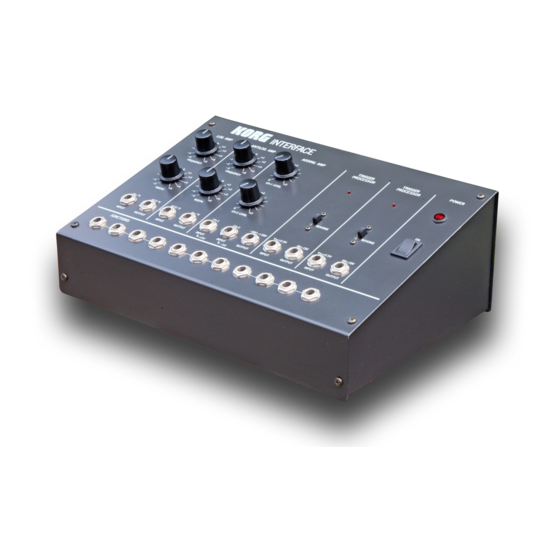
MS-02 OWNER 's MANUAL
1)
Introduction
2)
3)
4)
Using the Interface
5)
Caution
6)
7)
1) Introduction
"For complete connection compatibility between synthesizers.
The MS-02 is ideal if you want to upgrade your synthesizer by adding on other synthesizer units having
different kinds of keyboard control voltage and trigger signals. The built-in, fully adjustable log amp, anti-log
amp, and trigger processor ensure complete system flexibility and compatibility between any presently
voltage controlled synthesizer."
Thank you for choosing Korg equipment. In order to get the most out of your new MS-02, please read this
owner's manual carefully before use.
The Korg Interface MS-02 is designed for the purpose of connecting Korg MS-Series synthesizers with other
synthesizers available throughout the world. This sophisticated signal processor greatly enhances the
performance possibilities of the MS-Series.
Among presently available music synthesizers, there are two different types of control system used for the
VCO (voltage controlled oscillator) and EG (envelope generator). One of these systems is used by Korg and
Yamaha; the other is employed by every other synthesizer manufacturer. The Korg MS-02 provides you with
a way to change the control signals of one system into the control signals used in the other system. In this
way, it acts as an interface so that any two synthesizers can be used together, provided that the synthesizers
are equipped with the conventional input and output jacks for control voltage and trigger or gate signals.
2) Advantages of the Korg system
In the Korg Hz/V system, the VCO oscillator frequency is proportional to the control voltage. Other
synthesizers employ the OCT/V system, in which the oscillator frequency changes one octave for every one
volt (1V) change in the control voltage. Since an increase of one octave means that the frequency is
doubled, each increase of one volt in the control voltage means a doubling of VCO frequency.
The problem with the OCT/V system, used by every manufacturer except Korg and Yamaha, is that it must
employ a log amp in order to double the frequency for each one volt increase in the control voltage. Log amp
circuitry is unfortunately very unstable because of its sensitivity to temperature changes. This causes so
many problems that most professional musicians automatically assume that synthesizers always have
unstable pitch. When we developed out first Korg synthesizer, we decided that such a circuit was entirely
Advertisement
Table of Contents

Related Manuals for Korg MS-02


Summary of Contents for Korg MS-02
- Page 1 Thank you for choosing Korg equipment. In order to get the most out of your new MS-02, please read this owner's manual carefully before use.
- Page 2 The difference between the trigger (gate) signals of the two systems is clearest if you think of the trigger as a switch. In the lower diagram below is shown the Korg system ( ) of switching on EG operation (initiating operation), and the means by which the other system ( ) accomplishes the same thing.
- Page 3 (2) Set the octave (scale) selectors on both synthesizers to 8' and set the tuning knobs to the center position. (3) While playing the lowest note on the A keyboard, use the MS-02 Log Amp Frequency knob and the synthesizer B tuning knobs to match the pitch of B with that of A.
- Page 4 (3) While playing a note in the middle of the keyboard of synthesizer A, adjust the MS-02 Adding Amp Ch-1 level knob so that the pitch of B is the same as the pitch of A. For fine adjustment, use the tuning knobs on synthesizer B.
- Page 5 6) Caution (1) Before using the Log Amp or Anti Log Amp sections, turn on the MS-02 and let it warm up for about 10 minutes. (2) Since the MS-02 output may be affected by ambient temperature changes, avoid using near heating or cooling units.
- Page 6 3. ADDING AMPLIFIER Channel 1 level control Channel 2 level control Input Channel 1 Input Channel 2 Output 4. TRIGGER PROCESSORS x 2 Trigger indicator Reverse switch Input (Vth=+2.5V) Output (0V~+15V) 5. OTHERS Power switch Pilot lamp 6. JUNCTIONS 4 x 2 3 x 1 7.
Need help?
Do you have a question about the MS-02 and is the answer not in the manual?
Questions and answers