
Related Manuals for Meinberg GPS180SV


Summary of Contents for Meinberg GPS180SV
- Page 1 MANUAL GPS180SV GPS Receiver Eurocard 21st June 2017 Meinberg Radio Clocks GmbH & Co. KG...
-
Page 3: Table Of Contents
Skilled/Service-Personnel only: Replacing the Lithium Battery ....6 Technical Specifications GPS180SV Technical Specifications GPS Antenna ........ -
Page 4: Imprint
1 Imprint 1 Imprint Meinberg Funkuhren GmbH & Co. KG Lange Wand 9, 31812 Bad Pyrmont / Germany Phone: + 49 (0) 52 81 / 93 09 - 0 Fax: + 49 (0) 52 81 / 93 09 - 30 Internet: http://www.meinberg.de... -
Page 5: General Information Gps
2 General Information GPS The satellite receiver clock GPS180SV has been designed to provide extremly precise time to its user. The clock has been developed for applications where conventional radio controlled clocks can´t meet the growing requirements in precision. High precision available 24 hours a day around the whole world is the main feature of this system which receives its information from the satellites of the Global Positioning System. -
Page 6: Gps180Sv Features
UTC time scale since GPS was initiated in 1980. The current number of leap seconds is part of the navigation message supplied by the satellites, so the internal real time of the GPS180SV is based on UTC time scale. Conversion to local time and annual daylight saving time can be done by the receiver’s microprocessor if the corresponding parameters are set up by the user. -
Page 7: Asynchronous Serial Ports (Optional 4X Com)
COM0 is compatible with other radio remote clocks made by Meinberg. It sends the time string either once per second, once per minute or on request with ASCII ´?´ only. Also the interfaces can be configured to transmit capture data either automatically when available or on request. -
Page 8: Time Code (Option)
3 GPS180SV Features 3.7 Time Code (Option) 3.7.1 Abstract of Time Code The transmission of coded timing signals began to take on widespread importance in the early 1950´s. Espe- cially the US missile and space programs were the forces behind the development of these time codes, which were used for the correlation of data. -
Page 9: Irig Standard Format
3.7.3 IRIG Standard Format Date: 21st June 2017 GPS180SV... -
Page 10: Afnor Standard Format
3 GPS180SV Features 3.7.4 AFNOR Standard Format GPS180SV Date: 21st June 2017... -
Page 11: Assignment Of Cf Segment In Ieee1344 Code
IRIG-B time 1.) current firmware does not support leap deletion of leap seconds 2.) TFOM is cleared, when clock is synchronized first after power up. see chapter Selection of generated timecode Date: 21st June 2017 GPS180SV... -
Page 12: Generated Time Codes
3 GPS180SV Features 3.7.6 Generated Time Codes Besides the amplitude modulated sine wave signal, the board also provides unmodulated DC-Level Shift TTL output in parallel. Thus six time codes are available. a) B002: 100 pps, DCLS signal, no carrier BCD time-of-year... -
Page 13: Selection Of Generated Time Code
The pulse width DCLS signals shown in the diagramms "IRIG" and "AFNOR standard format" are coexistent to the modulated output and is available at the VG connector pin 13a with TTL level. 3.7.9 Technical Data Outputs: Unbalanced AM-sine wave-signal: (MARK) / 1 V (SPACE) into 50 Ohm DCLS signal: TTL Date: 21st June 2017 GPS180SV... -
Page 14: Installation
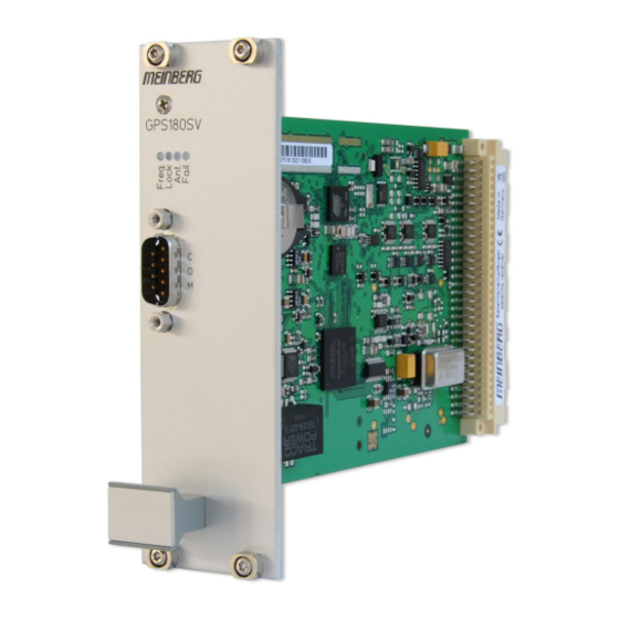
4 Installation 4 Installation 4.1 The Front Panel Layout Freq. LED blue: Initialisation phase GPS180SV green: "warmed up" - oscillator is adjusted off: Oscillator not adjusted yet Lock LED green: positioning complete Ant. LED red: no synchronization resp. no antenna connected... -
Page 15: Mounting The Gps Antenna
Up to four GPS180SV receivers can be run with one antenna/downconverter unit by using an optional an- tenna splitter. The total length of an antenna line from antenna to receiver must not be longer than the max. -
Page 16: Antenna Assembly With Surge Voltage Protection
GPS Antenna N-Norm female N-Norm male Cable Slot N-Norm male N-Norm female as short as possible N-Norm female Meinberg GPS N-Norm male N-Norm male female Ground lead to PE rail or BNC male female (Protective Earth) Cable ca. 1,5 mm Ø... -
Page 17: Power Supply
OCXO´s output frequency has been adjusted. Up to that time accuracy of frequency drops to 10-8 reducing the accuracy of pulses to +-5 s. Date: 21st June 2017 GPS180SV... -
Page 18: Safety Instructions
Danger of explosion in case of inadequate replacement of the lithium battery. Only identical batteries or bat- teries recommended by the manufacturer must be used for replacement. The waste battery must be disposed as proposed by the manufacturer of the battery. GPS180SV Date: 21st June 2017... -
Page 19: Technical Specifications Gps180Sv
6 Technical Specifications GPS180SV Receiver: 12 - channel C/A code receiver with external antenna/converter unit Antenna: antenna/converter unit with remote power supply refer to chapter "Technical specifications of antenna" Power Supply 15 V DC, continuous short circuit protection, automatic recovery... - Page 20 300, 600, 1200, 2400, 4800, 9600, 19200 Baud Framing: 7E1, 7E2, 7N2, 7O1, 7O2, 8E1, 8N1, 8N2, 8O1 default setting: COM0: 19200, 8N1 Meinberg Standard time string, per second COM1: 9600, 8N1 Capture string, automatically Time Code Outputs: Unbalanced modulated sine wave signal:...
- Page 21 ACCURACY OF FREQUENCY AND PULSE OUTPUTS: Date: 21st June 2017 GPS180SV...
- Page 22 6 Technical Specifications GPS180SV Steckerbelegung / Pin Assignment GPS180 / Signals / used Signals r e i Stecker: 96-polige VG-Leiste DIN 41612 a+b+c Connector: 96-pin VG-male DIN 41612 a+b+c IdentNr.: GPS180_V140_CON GPS180SV Date: 21st June 2017...
-
Page 23: Technical Specifications Gps Antenna
first IF frequency: 35.4 MHz Power Requirements: 12V ... 18V, @ 100mA (provided via antenna cable) Connector: N-Type, female Ambient Temperature: -40 ... +65 C Housing: ABS plastic case for outdoor installation (IP66) Physical Dimension: Date: 21st June 2017 GPS180SV... -
Page 24: The Program Gpsmon32
7 The program GPSMON32 7 The program GPSMON32 The program GPSMON32 can be used to monitor and programm all essential functions of Meinberg Receivers. The Software is executable under Windows 7, Windows Vista, Win9X, Win2000, WinXP and WinNT. To install GPSMON32 just run setup.exe from the included USB flash drive and follow the instructions of the setup... -
Page 25: Online Help
The online help can be started by clicking the menu item "Help" in menu Help. In every program window a direct access to a related help topic can be obtained by pressing F1. The help language can be selected by clicking the menu items German/English in the Help Menu Date: 21st June 2017 GPS180SV...
Need help?
Do you have a question about the GPS180SV and is the answer not in the manual?
Questions and answers