Table of Contents
Advertisement
™
RISE
Series
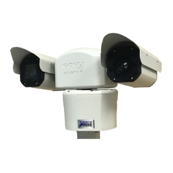
4260HD
Camera Positioning System
4290HD
Dual Spectrum Positioning System
Installation Manual
9995000 Rev A
youtube.com/CohuHD
LinkedIn.com/company/CohuHD
twitter.com/CohuHD
facebook.com/CohuHD
CohuHD.com
(858) 391-1800
© CohuHD Costar, LLC reserves the right to change specifications without notice
Advertisement
Table of Contents

Related Manuals for CohuHD Costar RISE 4260HD Series


Summary of Contents for CohuHD Costar RISE 4260HD Series
- Page 1 ™ RISE Series 4260HD Camera Positioning System 4290HD Dual Spectrum Positioning System Installation Manual 9995000 Rev A youtube.com/CohuHD LinkedIn.com/company/CohuHD twitter.com/CohuHD facebook.com/CohuHD CohuHD.com (858) 391-1800 © CohuHD Costar, LLC reserves the right to change specifications without notice...
- Page 2 - 2 -...
-
Page 3: Table Of Contents
Table of Contents 1.0 General Information 1.1 About This Document 1.2 Additional Information and Documents Related to the Camera System 1.3 Copyright/Intellectual Property Rights Statement 1.4 FCC Compliance 1.5 Support Services 2.0 Returns 2.1 Instructions 2.2 Shipment 3.0 Safety 3.1 Instructions 3.2 Grounding 4.0 Package Contents 5.0 Product Overview... - Page 4 7.2.11 Field Cables 8.0 Waterproof Coupler Assembly 8.1 Parts 8.2 Assembly 8.0 Best Practices 9.0 Installation 9.1 Installation Methods 9.1.1 Inverted Mount Configuration 9.2 4260HD and 4290HD Camera Systems Mounts 9.2.1 Mounting Brackets Dimensions 9.2.1.1 Large Pedestal Plate 9.2.1.2 Large Pedestal Adapter 9.2.1.3 Wall Mount Bracket, p/n 8425-7 9.2.1.4 Pole Mount Adapter, 8188275-002 9.2.2 4260 and 4290 Camera Systems Mounting Diagrams...
-
Page 5: General Information
For information on the camera system operation, see Operation manual. The manual is available from the CohuHD website at http://www.cohuhd.com/Support/Product-Documentation. 1.3 Copyright/Intellectual Property Rights Statement Copyright © 2020 CohuHD Costar, LLC. CohuHD Costar, LLC has intellectual property rights to technology ™ ™... -
Page 6: Returns
2.0 Returns 2.1 Instructions This item was thoroughly tested and carefully packed at the factory prior to shipping. Upon acceptance by the carrier, the carrier assumes responsibility for the item’s safe arrival. If you receive the item in a damaged condition, apparent or concealed, a claim for damage must be made to the carrier. -
Page 7: Safety
3.0 Safety 3.1 Instructions Warning: Do not remove the covers or housing. There are no user-serviceable parts inside. Warning: The Schrader Valves on the camera head's back plate are for factory use only. Do not attempt to add any gas to the camera head. Warning: PoE++ (Power over Ethernet) injectors used with this camera system may operate from 100-240 Vac. -
Page 8: Grounding
3.2 Grounding To provide protection against electrical surges induced by lightning, static charges, or any other cause, the camera and cabling system must be properly grounded to earth. For installation on a building, the camera must be bonded (that is, provided with a low impedance connection) to the building’s structural earth ground system. -
Page 9: Package Contents
4.0 Package Contents Upon opening of the products shipping package, please verify you have received the following items: 1. CohuHD 4260HD or 4290HD Camera System 2. Accessory Kit: Nitrile Gloves Anti-Seize Compound Mounting Bolt Hardware (4) 3. Documents: Thank You Letter Quick Start Guide Quality Control Checklist (QCL) IP67 RJ45 Coupler Assembly Instructions... -
Page 10: Product Overview
5.0 Product Overview 5.1 4260HD The 4260HD Camera System is an IP camera system contained within three independently sealed and environmentally protected sections. The camera system provides IP video streams with H.264 and JPEG compression. The positioning system provides continuous 360° pan (azimuth) motion range with 173° of tilt (elevation). -
Page 11: 4290Hd
5.2 4290HD The 4290HD Camera System is a dual head positioning system that provides simultaneous two types of streaming: HD visible spectrum imaging streaming standard resolution Long Wavelength Infrared (LWIR) night vision imaging streaming The camera system provides IP video streams with H.264 and JPEG compression. The positioning system provides continuous 360°... -
Page 12: Overall Dimensions And Mounting Base Hole Pattern
5.3 Overall Dimensions and Mounting Base Hole Pattern Use tables below to determine the dimensions of your camera system: 4260HD Series Configuration Model (first four digits) 4261 4262 4263 4264 4265 4266 4267 4268 4269 426A 426B 426C 4290HD Series Configuration Model (first four digits) -
Page 13: Configuration A Overall Dimensions In Inches (Mm)
5.3.1 Configuration A Overall Dimensions in inches (mm). 5.3.2 Configuration B Overall Dimensions in inches (mm). - 13 -... -
Page 14: Configuration C Overall Dimensions In Inches (Mm)
5.3.3 Configuration C Overall Dimensions in inches (mm). - 14 -... -
Page 15: Configuration D Overall Dimensions In Inches (Mm)
5.3.4 Configuration D Overall Dimensions in inches (mm). - 15 -... -
Page 16: Mounting Base Hole Pattern In Inches (Mm). Applies To All 4260Hd And 4290Hd
5.3.5 Mounting Base Hole Pattern in inches (mm). Applies to all 4260HD and 4290HD. - 16 -... -
Page 17: Factory Defaults
6.0 Factory Defaults 6.1 Factory Default IP Address and Settings The camera is shipped with the following network settings: IP Address: 192.168.2.150 Subnet mask: 255.255.255.0 Gateway: 192.168.2.1 6.2 User Names and Passwords Note: The camera is no longer shipped with a username and password. The first user is admin who has to create a password and then login. -
Page 18: Connections
7.0 Connections 7.1 Interconnections The following are interconnection diagrams for 4260HD and 4290HD camera systems. Note: The diagrams show the 4260HD series but apply to both camera systems. 7.1.1 Typical, PoE++ Powered - 18 -... -
Page 19: Typical, Ac Powered
7.1.2 Typical, AC Powered - 19 -... -
Page 20: 4260Hd And 4290Hd Models And Available Cable Functions
7.2 4260HD and 4290HD Models and Available Cable Functions The camera system is built with one or two cables attached to the camera base for electrical connection. The model number identifies the type(s) of cable(s) the camera system requires. The camera system can be ordered with a combination of two cables. The following pictures show camera models with associated Pigtail Cables: 7.2.1 4260HD Models and Cables - 20 -... -
Page 21: 4290Hd Models And Cables
7.2.2 4290HD Models and Cables 7.2.3 Camera Connector Configuration Table 4260HD 4261 4262 4263 4264 4265 4266 4267 4268 4269 426A 426B 426C Series Connector Pinout Schematic 4290HD 4291 4292 4293 4294 4295 4296 4297 4298 4299 Series - 21 -... -
Page 22: Rj45 Pinout Table
7.2.4 RJ45 Pinout Table RJ45 Connector Pinouts Function Pinout A Pinout D ETHERNET TX+, PoE++ [-] ETHERNET TX+ ETHERNET TX-, PoE++ [-] ETHERNET TX- ETHERNET RX+, PoE++ [+] ETHERNET RX+ ETHERNET RX-, PoE++ [+] ETHERNET RX- PoE++ [+] PoE++ [+] PoE++ [-] PoE++ [-] 7.2.5 Prepped Accessory Cable Wire Definitions Table... -
Page 23: Ms Pigtail Cable Pinouts Table
7.2.6 MS Pigtail Cable Pinouts Table MS Cable Function Connector Pinout C Pinout F Pinout G Pinout H Pinout I DIO 1 DIO 1 DIO 1 DIO 1 DIO 1 DIO 2 DIO 2 DIO 2 DIO 2 DIO 2 DIO 3 DIO 3 DIO 3... -
Page 24: Amp Pigtail Connector Pinouts Table
7.2.7 AMP Pigtail Connector Pinouts Table AMP Cable Function AMP Connector Pinout J Pinout K Pinout L I/O COMMON I/O COMMON RS422 TX- RS422 RX+ RS422 RX+ CHASSIS RS422 RX- RS422 RX- ETHERNET TX- RS422 TX+ RS422 TX+ ETHERNET TX+ RS422 TX- RS422 TX- RS422 TX+... -
Page 25: 18-Pin Ms Type (Metal) Connector And Its Mating System Cable Connector
7.2.8 18-pin MS Type (Metal) Connector and its Mating System Cable Connector Camera connector: CohuHD p/n 1310230-117 Mating connector: CohuHD p/n 1310230-111 (ordered separately) 7.2.9 Amp Type (Plastic) Connector Kit and its Mating System Cable Connector Kit Camera connector kit: CohuHD p/n 8498-1 Mating connector kit: CohuHD p/n 8498-3 - 25 -... -
Page 26: Digital Inputs/Outputs (Dio)
7.2.10 Digital Inputs/Outputs (DIO) The camera system can be configured with up to four inputs or four outputs. Each pin can be set as an input or output. The number of inputs/outputs depends on which I/O cable is ordered: Cable with stripped leads: Four inputs or four outputs are available. Cable with MS connector: Three inputs or three outputs are available. -
Page 27: Field Cables
Digital Output Wiring Example 7.2.11 Field Cables All system cables must be shielded, and the shield(s) must be bonded to earth ground. All Ethernet wiring must be done in accordance with TIA/EIA 568-C standards. To build the camera system cables, CohuHD recommends: For Ethernet/PoE++: CohuHD p/n 7610179-001. - Page 28 Ethernet Cable Wiring to a Hub, Switch, or Router (Straight Wiring) Corresponding RJ-45 Ethernet Function Ethernet Pins This Ethernet wiring is intended to connect directly to a hub, switch, or router. For connection directly to a PC, it will be necessary to use either a crossover cable or a crossover adapter. Note: For clarity, only signal lines are shown.
- Page 29 RS422 Cable Wiring to B&B Converter Camera Side Converter Side RS422 Camera RS422 Device RS422 RX+ TD(B) RS422 RX- TD(A) RS422 TX+ RD(B) Warning: Connecting certain cables to the 4260HD or 4290HD Series camera systems can result in permanent damage to the camera. Do not connect any cable to a 4260HD or 4290HD camera system without verifying compatibility first.
-
Page 30: Waterproof Coupler Assembly
8.0 Waterproof Coupler Assembly 8.1 Parts The coupler comes assembled with extra two large diameter cable seals for thicker cables. The coupler package consists of the following parts: 1. Sealing Nut (2 pcs) 2. Seal a. a. Small diameter cable (2 pcs) – already inserted b. - Page 31 2. If the RJ45 plug has a strain-relief boot, push it away from the RJ45 plug. The strain-relief boot will not be used. 3. Pass the cable through the Sealing Nuts (1) 4. Pass the cable through the Sealing Collar (3). 5.
- Page 32 Now attached the Sealing Nut (1) to the connected Sealing Collar (6). Warning: Tighten by hand and do not over-tighten. Using tools and over-tightening may split the Seal’s notch, which compromises the waterproof assembly. The Seal’s notch should join without a flaw. 11.
-
Page 33: Best Practices
8.0 Best Practices The purpose of this section is to provide recommendations regarding the proper selection and use of Surge Protection Devices (SPDs) in CCTV systems. This section is not meant to provide guidance for SPDs selection, placement, and use on incoming utility power. -
Page 34: Installation
9.0 Installation 9.1 Installation Methods The 4260HD and 4290HD camera systems are available in the following mount configurations: Standard Inverted 9.1.1 Inverted Mount Configuration When installed in the inverted position, the camera orientation and control functions are reconfigured through the software via browser interface. Use the following steps to reconfigure the software for inverted mounting: Note: No hardware adjustment is required. -
Page 35: Mounting Brackets Dimensions
9.2.1 Mounting Brackets Dimensions All dimensions in inches (mm). 9.2.1.1 Large Pedestal Plate 9.2.1.2 Large Pedestal Adapter - 35 -... -
Page 36: Wall Mount Bracket, P/N 8425-7
9.2.1.3 Wall Mount Bracket, p/n 8425-7 - 36 -... -
Page 37: Pole Mount Adapter, 8188275-002
9.2.1.4 Pole Mount Adapter, 8188275-002 - 37 -... -
Page 38: 4260 And 4290 Camera Systems Mounting Diagrams
9.2.2 4260 and 4290 Camera Systems Mounting Diagrams The following are mounting diagrams for 4260HD and 4290HD camera systems. Note: The diagrams show the 4260HD series but apply to both camera systems. 9.2.2.1 Large Pedestal Adapter for the PoE and 24 Vac Power Option Use the large pedestal adapter for additional mounting hole patterns. -
Page 39: Wall Mount
9.2.2.3 Wall Mount Use the mount adapter and wall mount for installation to a wall. "Wall Mount Bracket, p/n 8425-7" on page 36. 9.2.2.4 Pole Mount Use the mount adapter, wall mount, and large pole mount for installation to a pole. "Pole Mount Adapter, 8188275-002"... -
Page 40: Installation Procedure
9.3 Installation Procedure Warning: Always support a camera until it has been fastened securely. Caution: Do not use the cable to support the weight of the camera. Provisions must be made for routing the system cable up to the camera system location: Pole: If the cable routes up through the pole, support the cable inside the pole to strain relieve the cam- era connector. - Page 41 Install the camera system: Position the camera on the mount adapter/plate or pedestal and secure it with the 1/4-inch fasteners (supplied). Note: For easy installation, look for two alignment marks on the base housing for hole location. Ground the camera: Connect the grounding wire to the grounding screw on the camera's base.
-
Page 42: Camera Urls
9.0 Camera URLs 9.4 Camera Default Passwords User = admin Password = admin 9.5 Network Video Ports Required for RTSP 554 - RTSP uses TCP or UDP as its transport protocol. UDP Ports: Self-Determined 9.6 Video Stream Connection URL’s Note: Do not include brackets < > in connection URL strings. RTSP/RTP Unicast and RTSP Interleaved Connection String: rtsp://<ipaddress>/<Presentation Name>... -
Page 43: System Requirements
10.0 System Requirements 10.1 Requirements In order to test the camera system you need the following items: Laptop or desktop computer 100/1000BASE-T network card installed in the computer Latest Chrome, Firefox, or Edge web browser 100/1000BASE-T network switch or hub Cat5e or Cat 6 cable 10.2 Recommended Computer Specifications The following are recommended computer specifications to run and operate a camera system:... -
Page 44: Optional Accessories
11.0 Optional Accessories The following optional accessories are recommended by CohuHD and can be purchased with the camera system. Mounts Wall: CohuHD p/n 8425-7 Pole: CohuHD p/n 8503-0 PoE ++ Injectors CohuHD p/n 7412007-003 Field Connectors MS Mating Connector: CohuHD p/n 1310230-111. AMP Mating connector kit: CohuHD p/n 8498-1 Waterproof RJ45 Coupler Waterproof RJ45 Coupler: CohuHD p/n 7610203-002. -
Page 45: Service
11.0 Service The 4260HD and 4290HD Series are designed for long-term unattended use and contains no user-serviceable parts. In the event of product failure, the system should be removed from the site and returned to an authorized service center for repair. Note: Contact CohuHD field service department at (858) 391-1800 option 2 for service assistance or go to http://www.cohuhd.com/Contact/Return-Authorization-Request for obtaining a Return Authorization... -
Page 46: Camera Head Housing Pressurization
11.2 Camera Head Housing Pressurization Before shipping from the factory dry packs of desiccant are secured inside the camera housing. The housing is then sealed and purged with dry nitrogen to remove moist air from inside the housing. The purging process provides an internal relative humidity of 5% or less. -
Page 47: Wiper Unit
11.3 Wiper Unit The camera system is available with a wiper arm option to keep the visible spectrum camera head window clear in inclement weather. The wiper design allows for easy replacement of the wiper arm. Wiper Arm Replacement To replace a worn or deteriorated wiper arm, use the following parts: Wiper Arm Assembly: CohuHD p/n 8190-5 Set Screw: Part of the wiper arm assembly Hex wrench tool: 1.5 mm... -
Page 48: Troubleshooting
11.4 Troubleshooting The table below identifies possible issues that could occur with the camera, and corrective actions on how to resolve them. Note: If the issue persists after following the corrective actions, contact CohuHD field service department at (858) 391-1800 option 2 for additional assistance. Problem/Symptom Possible Cause Correction... -
Page 49: Warranty
12.0 Warranty Please refer to the CohuHD website for product warranty information: http://www.cohuhd.com/Support/Warranty. - 49 -... - Page 50 For more information please visit us at: www.CohuHD.com - 50 -...
Need help?
Do you have a question about the RISE 4260HD Series and is the answer not in the manual?
Questions and answers