
Subscribe to Our Youtube Channel
Related Manuals for CohuHD Costar 4220HD


Summary of Contents for CohuHD Costar 4220HD
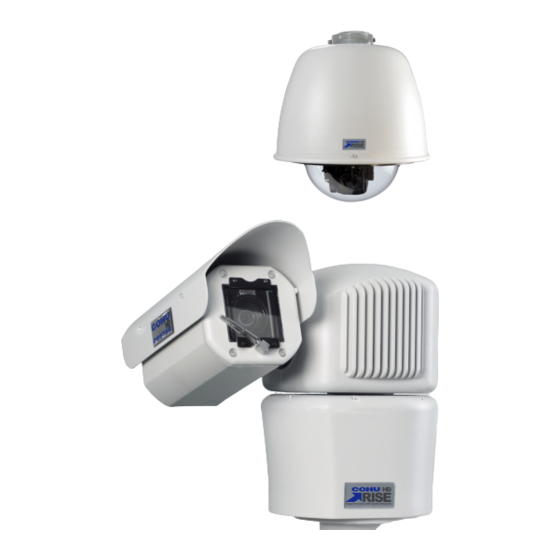
- Page 1 RISE™ Series 4220HD Dome Positioning System 4260HD Camera Positioning System Operation Manual 6x-1119A www.CohuHD.com...
- Page 2 - 2 -...
-
Page 3: Table Of Contents
Table of Contents 1.0 General Information 1.1 About this document 1.2 Additional information and documents related to the camera system 1.3 Copyright/Intellectual Property Rights Statement 1.4 FCC compliance 1.5 Support services 1.6 Returns 1.7 Shipment 2.0 Getting Started 2.1 Recommended Computer Specifications 2.2 System Requirements 2.3 Factory Default IP Address and Settings 2.4 Factory Default User Names and Passwords... - Page 4 3.3.5.3 FTP Servers 3.3.5.4 Action Engine Configuration 3.3.5.5 Action Engine Settings 3.3.6 Users 3.3.6.1 User Settings 3.3.7 Network 3.3.7.1 Network Settings 3.3.7.2 Port Settings 3.3.7.3 Serial Settings 3.3.8 Date and Time 3.3.8.1 Date and Time Settings 3.3.9 On-Screen Display (OSD) 3.3.9.1 OSD Wizard 3.3.9.2 OSD Settings 3.3.9.3 OSD Banner Settings...
-
Page 5: General Information
For information on the 4260HD camera system installation, see Installation manual 6x-1114. The manual is available from the CohuHD Costar website at: For information on the 4220HD camera system installation, see Installation manual 6x-1116. The manual is available from the CohuHD Costar website at: http://www.cohuhd.com/Support/Product-Documentation... -
Page 6: Returns
1.6 Returns This item was thoroughly tested and carefully packed at the factory prior to shipping. Upon acceptance by the carrier, the carrier assumes responsibility for the item’s safe arrival. If you receive the item in a damaged con- dition, apparent or concealed, a claim for damage must be made to the carrier. If a visual inspection shows damage upon receipt of this shipment, it must be noted on the freight bill or express receipt and the notation signed by the carrier’s agent. -
Page 7: Getting Started
2.0 Getting Started 2.1 Recommended Computer Specifications The following are recommended computer specifications to run and operate a camera system: CPU: Intel i7-860S 2.53 GHz or better Operating system: Windows 7 or later Memory: 4GB DDR3@1066MHz or better Hard Drive: 7200 rpm – minimum speed with sufficient free space Video card: NVIDIA®... -
Page 8: Assigning The Static Ip Address
2.5 Assigning the Static IP Address Important: In order to make changes in network settings in the local machine the user must be logged in as Administrator. Please contact your local IT department if you do not have Admin privileges. Set your computer IP address to the same subnet as the camera system IP address: 1. - Page 9 5. Click the Close button to close the Local Area Connections Properties dialog box. 6. Click the Close button to close the Local Area Connection Status dialog box. - 9 -...
-
Page 10: Assigning The New Camera Ip Address
2.6 Assigning the New Camera IP Address No two devices on a single Ethernet network can have the same IP address. Use the following steps to change a camera IP address before a second camera is added to the subnet. 1. -
Page 11: Using The Rise Camera Discovery Tool
CohuHD cameras. The MAC address of the camera is the serial number of the camera which can be found on the serial number label. The label location is on the back of the camera head for 4260HD and on the housing for 4220HD. Periodic Scan: Check the box to enable or disable periodic scans. - Page 12 Scan Interval: Move the slider indicator to establish a desired scan interval. A minimum interval is one second. To schedule scans: Check the Periodic Scan box. Move the slider indicator to set a scan interval value. Note: If the Periodic Scan box is unchecked, the scan will be initiated only once. 3.
-
Page 13: Accessing The Camera Using Web Interface
5. For Internet Explorer only: The camera will attempt to install an ActiveX control on your PC. Allow the camera to install ActiveX control by clicking on the prompt “This website wants to install the following add-on: CohuRTPControl.cab from CohuHD Costar.” Click the Install button. 6. Type user name and password. Click OK. -
Page 14: Users' Accounts
7. The Home page appears. 2.9 Users' Accounts Four users’ accounts are defined in the web interface to allow differ ent levels of access. Those accounts are: Administrator Operator User Anonymous - 14 -... -
Page 15: Operation
3.0 Operation 3.1 Home Page Use the Home page to view the video and control the camera. View the Video Choose a profile from the drop-down list. Default is Profile 1. See "Profile Settings" on page 39 to configure a profile. Choose a transport mode from the top of the Control Panel. - Page 16 Control Panel: Use the panel to move the camera with the PTZ control and to have quick access to frequently used controls. Use the following screen mode options to view the video: To hide/show the browser information - click F11. To hide/show the Setup Panel - click the Setup tab.
- Page 17 To see full screen video - click the top blue bar with profile name and user name. … Click the Esc key to return to the previous screen. - 17 -...
-
Page 18: Control Panel
3.2 Control Panel The user must be logged in as Administrator, Operator or User to use the control panel. Click on the Control Panel tab to show/hide the control panel. The following tabs are available on the control panel: Presets and Tours Advanced 3.2.1 PTZ Control The user must be logged in as Administrator, Operator or User to use the PTZ control. - Page 19 Positioner Control Pan and Tilt (PT) Menu: Click the button to reveal the PT direction arrows. PT Arrow Buttons: Click one of the button to move the camera in the desired direction. Zoom In/Out Buttons: Press the Zoom In button to zoom in.
-
Page 20: Presets And Tours Control
3.2.2 Presets and Tours Control The user must be logged in as Administrator, Operator or User to use the Presets and Tours control. Click the Presets and Tours tab to bring the Presets and Tours control panel to the screen. The Presets and Tours panel allows users to have a quick access to already programmed presets and tours. -
Page 21: Advanced Control
3.2.3 Advanced Control The user must be logged in as Administrator, Operator or User to use the Advanced control. Click the Advanced tab on the Control panel to bring the Advanced control to the screen. The following buttons and controls are available on the Advanced tab: Defog: Select one of the modes: Medium High... -
Page 22: Setup Panel
3.3 Setup Panel Click on the Setup tab to show/hide the Setup panel. The Setup panel is used for configuring the camera. The following tabs are available from the camera con- figuration menu on the left side of the Setup tab: Image a. - Page 23 User a. User Settings Network a. Network Settings b. Port Settings c. Serial Settings Date and Time a. Date and Time Settings On-Screen Setup a. OSD Wizard b. OSD Settings c. OSD Banner Settings d. OSD Sector Settings e. OSD Logo Settings Privacy Mask a.
-
Page 24: Image
3.3.1 Image The user must be logged in as Administrator or Operator in order to make changes on the Image page. Use the Image tab to configure lens and exposure settings and other image controls. Click the Image tab to view the following panels: Lens Settings Exposure Setting Defog Settings... - Page 25 increase to a point where the camera will change to the Black and White mode, and the IR cut filter will be removed from the light path. As the scene illumination increases, the camera gain will decrease to a point where the camera will change to the Color mode, and the IR cut filter will be inserted into the light path.
-
Page 26: Defog Settings
Backlight Compensation (BLC) Select one of the modes: Important: When BLC is On, WDR is Off. The BLC alters the automatic exposure control programming to prevent a bright background from making dark parts of the image too dark. A bright background can cause the automatic exposure control to make a dark area of the scene too dark. -
Page 27: Advanced Settings
detected there is minimal compensation. The Auto mode has limitations under the following conditions: Image is not in focus Images are too dark or too bright because of the iris control related function BLC is turned On WDR is turned On The scene has low contrast The scene has high contrast Manual: Select one of three manual levels of enhancement, depending on fog thickness:... - Page 28 Sharp Sharpest White Balance: Select one of the modes: Manual: The Manual white balance prevents the automatic white balance compensation and allows the operator to manually change the red and blue levels for a specific light condition. Auto (Normal, Sodium, Mercury): The Auto white balance will automatically compensate for changing light conditions to maintain correct color reproduction, especially during the transition from day to night or from night to day.
-
Page 29: Positioner
3.3.3 Positioner The user must be logged in as Administrator or Operator in order to make changes on the Positioner page. Use the Positioner tab to configure presets, tours and other positioner controls. Click the Positioner tab to view the following panels: Presets Settings Tours Settings Park Settings... - Page 30 sets list in the PTZ control, and in the Available Presets table in the Tour Settings panel. 5. Click the Cancel button to cancel the create preset operation. To delete a preset: 1. Select a preset name in the Presets table. 2.
-
Page 31: Tour Settings
3.3.3.2 Tour Settings A tour is a group of presets that are visited in a defined sequence. The system supports 256 tours. Each tour can have a maximum of 32 presets. Each preset in a tour has its individual dwell time and pan and tilt speed. The minimum dwell time is 1 second and the maximum dwell time is 3600 seconds (one hour). - Page 32 5. Add presets to the tour: a. Select a tour in the Tour table. b. Select a preset from the Available Presets list. c. Click the Add button . The preset will be added to the Included Presets table. d. Add all desired presets to the tour. 6.
-
Page 33: Park Settings
3.3.3.3 Park Settings The camera system can be set to automatically move to a preset or start a tour after a selected interval of inactivity. Note: Preset(s) or Tour(s) must be established in order to create a Park Position. Set the Park Position Use the steps below to set the Park Position: 1. -
Page 34: Positioner Settings
On: Choose the On option for inverted installation of the camera system. Off: Choose the Off option for upright installation. Auto Flip (Only 4220HD): This function enables the PTZ dome camera to flip the image 180 degrees and enables the operator to see the target when it moves under the camera. - Page 35 Choose one of two options: On: Choose the On option to invert the image when the camera system reaches a mechanical stop at -90°. Off: Choose the Off option to disable the Flip function. High Wind/Vibration: Enabling the feature reduces the traveling speed between presets. Choose one of two options: On: Choose the On button to enable the High Wind/Vibration mode.
-
Page 36: Media
3.3.4 Media The user must be logged in as Administrator or Operator to make changes on the Media page. Use the Media tab to configure video profiles. Click the Media tab to view the following panels: Media Wizard Media Utilization Profile Settings Stream Settings Advanced Settings... - Page 37 2. Choose the preference for picture quality. 3. Choose video resolution. 4. Type a profile name: - 37 -...
-
Page 38: Media Utilization
5. Click the Finish button to complete the stream and profile setup. Note: The profile name will be added to the Profile Name list on the Profile Settings Panel. The stream name will be added to the Stream Name lists on the Profile Settings and Stream Settings panels. -
Page 39: Profile Settings
3.3.4.3 Profile Settings The user must be logged in as Administrator or Operator in order to make changes on the Profile Set- tings page. Profiles can be defined by using one of the two panels: 1. Media Wizard: Use the Media Wizard panel to create simultaneously a profile and a stream associated with this profile. - Page 40 To delete a profile: 1. Select a profile from the Profile Name list. 2. Click the Delete button. Note: Cannot delete Profile 1 or Profile 2. To remove a stream form the profile: 1. Select a profile from the Profile Name list. 2.
-
Page 41: Stream Settings
3.3.4.4 Stream Settings The user must be logged in as Administrator or Operator in order to make changes on the Stream Set- tings page. To add a stream to the profile: 1. Click the Add button to add a new stream name.The stream name will be added to the Stream Name list. - Page 42 Codec The camera system supports the following compression standards: H.264 (Baseline, Main and High profiles) MJPEG 1. H.264: Reduces bandwidth and storage consumption significantly. H.264 codec is the most frequently recommended codec for high-definition video applications. a. Baseline: Baseline is the least complex of the three profiles and places the least demand on a decoder.
- Page 43 Bit Rate Control Choose: 1. Variable Bit Rate (VBR) or Constant Bit Rate (CBR) 1. Variable Bit Rate (VBR) Note: When the VBR encoding method is used, the Minimum and Maximum Quality Range and the Maximum Bit Rate must be specified. The GOV Length control is enabled. Variable Bit Rate (VBR) is an encoding method that ensures consistent video quality throughout an encoded file.
- Page 44 3. MJPEG Codec Configuration Quality: When MJPEG codec is selected, use the Quality knob to control the image quality. 50% is a recommended number. MJPEG quality settings are a tradeoff between image quality and bandwidth. Multicast Address: Multicast is used for a large number of simultaneous viewers and for the most effi- cient usage of bandwidth.
-
Page 45: Advanced Settings
3.3.4.5 Advanced Settings Use this panel to configure quality and file size of snapshots produced by the camera. Snapshot Resolution: Choose the required resolution for your snapshot from the drop-down list: 1920 x 1080 1280 x 720 720 x 576 720 x 480 640 x 480 320 x 240... -
Page 46: Action Engine
3.3.5 Action Engine The user must be logged in as Administrator in order to make changes on the Action Engine page. Click the Action Engine tab to view the following panes: Action Engine Wizard Email Servers FTP Servers Action Engine Configuration Settings 3.3.5.1 Action Engine Wizard Action Engine can be configured by using one of two panels:... - Page 47 2. Trigger Configuration: Type the trigger name in the text box. Depending on the trigger, select the event (indicate the frequency, date, time) that will initiate the Action Engine trigger from the drop-down list.Click the Next button. 3. Action: Choose an action. Click the Next button. - 47 -...
- Page 48 4. Action Configuration: Type the action name in the text box. If you are using email or FTP, the best practice is to validate connection. Click the Next button. 5. Complete: Click the Finish button. - 48 -...
-
Page 49: Email Servers
3.3.5.2 Email Servers Create Email Server 1. Click the Add button. A new dialog box will appear. 2. Fill the following fields: Server Name: Enter the name of the SMTP server. This name will be used to identify the server for later actions. Server Address: Enter the IP Address or URL of the SMTP server. - Page 50 6. To delete or edit the server: a. Highlight the desired line in the Available Email Servers table. b. Click the Delete or Edit button. - 50 -...
-
Page 51: Ftp Servers
3.3.5.3 FTP Servers Create FTP Server 1. Click the Add button. A new window will appear. 2. Fill the following fields: Server Name: Enter the name of the SMTP server. This name will be used to identify the server for later actions. Server Address: Enter the IP Address or URL of the SMTP server. -
Page 52: Action Engine Configuration
6. To delete or edit the server: a. Highlight the desired line in the Available Email Servers table. b. Click the Delete or Edit button. 3.3.5.4 Action Engine Configuration The user must be logged in as Administrator in order to make changes on the Action Engine Con- figuration page. - Page 53 The camera supports the following actions when a trigger happens: Display OSD Event Text: Displays an alarm OSD text External Output: Sends a digital signal to an external device Go to Preset: Activates a Preset Send Email: Sends an email notification. SMTP (Simple Mail Transfer Protocol) server must be configured Send Snapshot via FTP: Creates and uploads one or more snapshots to an FTP server Send Snapshot via Email: Sends an email notification with one or more snapshots...
- Page 54 Maintenance: This trigger allows the camera to execute a sequence of user programmed actions when one of the maintenance events happen (e.g. low or high temperature, low pressure). Preset Reached: This trigger allows the camera to execute a sequence of user programmed actions when the camera reaches a user configured preset.
- Page 55 How to Configure an Action 1. Click the Add button from the right column. A new dialog box will appear. 2. Select one of the following action types from the drop-down menu: Display OSD External Output Go to Preset Send Email Send Snapshot via FTP Send Snapshot via Email Send Snapshot via Text (MMS)
- Page 56 Action Name: Type an action name. SMTP (Simple Mail Transfer Protocol) Server: SMTP server is used to verify an action later. Select the server from the drop-down list. Email Sender: Enter the email address from where email is sent. Email Recipients: Enter the email addresses where you wish to send email notifications. In case of multiple recipients, the addresses must be separated by commas, spaces or semicolons.
- Page 57 Snapshot Filename: Configure the name of the attached image. To configure the Snapshot Filename: 1. Click the Configure button. The Create Filename Format dialog box appears. 2. Select the field name from the drop-down list. The field name will be added to the Filename For- mat box.
- Page 58 To configure the Email Subject: 1. Click the Configure button. The Create Subject Format dialog box appears. 2. Select the field name from the drop-down list. The field name will be added to the Subject For- mat box. Each field will be populated dynamically when the email is sent. Fields will appear in the email subject separated by _ (underscore).
- Page 59 Send Snapshot via Text (MMS) The camera system can be configured to capture one or more snapshots (JPEG file) in response to a trigger and transfer the image to an MMS device. Action Name: Type an action name. SMTP (Simple Mail Transfer Protocol) Server: SMTP server is used to verify an action later. Select the server from the drop-down list.
- Page 60 1. Click the Configure button. The Create Filename Format dialog box appears. 2. Select the field name from the drop-down list. The field name will be added to the Filename For- mat box. Each field will be populated dynamically when the email is sent. Fields will appear in the email subject separated by _ (underscore).
- Page 61 1. Click the Configure button. The Create Subject Format dialog box appears. 2. Select the field name from the drop-down list. The field name will be added to the Subject For- mat box. Each field will be populated dynamically when the email is sent. Fields will appear in the email subject separated by _ (underscore).
-
Page 62: Action Engine Settings
3.3.5.5 Action Engine Settings When an action is triggered, all the actions associated with it are executed in the order in which they are programmed by the user. The Action Engine implements three user selectable schemes to handle simultaneous event triggers. Trigger Queuing: Select one of three options to handle simultaneous event triggers: Priority: When two events are triggered simultaneously or a new event is triggered while actions of a previous event are being executed, the action engine will immediately clear its cur-... -
Page 63: Users
3.3.6 Users The user must be logged in as Administrator to make changes on the Users page. Use the Users tab to set the user names, passwords and access level. Click the Users tab to view the following panel: User Settings 3.3.6.1 User Settings Authentication Four user accounts are defined in the web interface to allow different levels of access:... - Page 64 Creating a New User 1. Click the Add button. The Add a New User window will appear. 2. Enter User Name in the User Name box. 3. Select the appropriate access level from the drop-down Security group list. 4. Enter a password. Note: Password complexity is not required. 5.
- Page 65 Editing User Properties 1. From the Username list, click edit. The Edit User Properties window will appear. 2. Enter a new user name. 3. Choose a new Security Group. 4. Click the Save User Settings button. Deleting a User 1. From the user account list, click delete. - 65 -...
-
Page 66: Network
3.3.7 Network The user must be logged in as Administrator to make changes on the Network page. Use the Network tab to configure the network settings. Click the Network tab to view the following panels: Network Settings Port Configurations Serial Configuration 3.3.7.1 Network Settings The Network Settings panel allows the user to assign IP information through a DHCP (Dynamic Host Configuration Protocol) server or manually. - Page 67 Note: Device names cannot start with a number unless they are part of a dotted octet IP address. IP Address: Enter the Static IP address assigned to the camera. Be sure it is not already assigned on your network. Subnet Mask: Enter the Subnet Mask used to define the size of the subnet. Gateway: Enter the Default Gateway address.
-
Page 68: Port Settings
b. DHCP Maximum Transmission Unit (MTU): The MTU is the largest physical packet size that a network can transmit. Any messages larger than the MTU are divided into smaller packets before being sent. MTU sizes are inherent properties of physical network interfaces and the values are fixed for each phys- ical technology. -
Page 69: Serial Settings
Cohu with Header: 1234 Cohu with no Header: 1233 Cohu T: 1234 HTTP Port: The default HTTP (Hypertext Transfer Protocol) port number is 80 and can be changed to any port within the range 1024 to 65535. HTTPS Port: The default HTTPS (HTTP over SSL or HTTP Secure) port number is 443 and can be changed to any port within the range 1024 to 65535. - Page 70 Cancel: Returns to the previously saved state. Save: Stores current settings permanently. Default: Restores the factory default settings. - 70 -...
-
Page 71: Date And Time
3.3.8 Date and Time The user must be logged in as Administrator to make changes on the Date and Time page. Use the Date and Time tab to set the time from the clock on your computer or synchronize a camera clock with a NTP server. -
Page 72: On-Screen Display (Osd)
3.3.9 On-Screen Display (OSD) The user must be logged in as Administrator or Operator to make changes on the OSD page. Use the OSD tab to display overlay elements on the video, a logo, and configure sectors. Click the OSD tab to view the following panels: OSD Wizard OSD Settings OSD Banner Settings... - Page 73 2. If the text element is chosen, type the text. Click the Next button. 3. Choose a font size of the element. Click the Next button. - 73 -...
- Page 74 4. Choose font color of the element. Click the Next button. 5. Choose a background for the element. Click the Next button. - 74 -...
-
Page 75: Osd Settings
6. Choose location for the element. 7. Click the Finish button. 8. Add another element if you wish. 3.3.9.2 OSD Settings The camera system cam be programmed to display up to eight elements, with particular information. Each element can be independently configured. The following eight elements are available to be superimposed on the video: 1. - Page 76 5. Date/Time: Current system date and time on the camera 6. Sector: Current active sector title 7. Maintenance: Current system temperature and pressure 8. Event: Current active action ( Action Engine) To add an OSD element to the stream, use the following steps: 1.
- Page 77 To edit the element: Select the element and click the Edit button. Make changes and click the Save button. To delete the element from the stream: Select the element and click the Remove button. The element will be remove. - 77 -...
-
Page 78: Osd Banner Settings
3.3.9.3 OSD Banner Settings The camera system can be programmed to display two banners: one across the top and one across the bottom. Each banner can be displayed and configured independently . Banner Size: 6 - 8% of the image height Banner Position: top or bottom or both Banner Color: black Up to eight elements can be added to the banner:... - Page 79 To display the banner: 1. In the Top or Bottom Banner Sections, choose the option On. The banner will be displayed. Note: Each banner can be displayed and configured independently . To add an OSD element to the banner, use the following steps: 1.
-
Page 80: Osd Font Settings
period ( . ) comma ( , ) colon ( : ) at sign (@) slash mark ( / ) If the Date element is chosen, select OSD date format from the drop-down list. Sup- ported formats are: MM-DD-YYYY HH:MM:SS [12 | 24 Hr] DD-MM-YYYY HH:MM:SS [12 | 24 Hr] YYYY-MM-DD HH:MM:SS [12 | 24 Hr] MM-DD-YY HH:MM:SS [12 | 24 Hr]... -
Page 81: Osd Sector Settings
1. In the OSD Font Settings panel, click the Add button. The Choose File to Upload dialog box dis- plays. 2. Choose the folder containing the font to be uploaded. 3. Select the font file (.ttf extension), and then click Open. 4. -
Page 82: Osd Logo Settings
4. Pan the camera to the left edge of the area to be labeled. Click the Set Left Limit button. Left limit pan degrees will be added to the left limit line. 5. Pan the camera to the right edge of the area to be labeled. Click the Set Right Limit button. Right limit pan degrees will be added to the right limit line. - Page 83 To upload the logo: 1. Click the Add button. 2. Select the logo file to upload. 3. Double-click the file to upload the logo to the camera. Check for the file name in the Logo Name section. 4. From the Logo Position section, use slides to position the logo. Range is left to right and bottom to top.
-
Page 84: Privacy Mask
3.3.10 Privacy Mask The user must be logged in as Administrator or Operator to make changes on the Privacy Mask page. Use the Privacy Mask tab to configure masks. Click the Privacy Mask tab to view the following panels: Privacy Mask Wizard Privacy Mask Add / Delete Privacy Mask Settings Privacy Masks are used to conceal sensitive areas that should not be captured by the camera. - Page 85 2. Choose the preference for picture blurring. Click the Next button. 3. Choose your mask opacity. Click the Next button. 4. Choose your mask brightness. Click the Next button. - 85 -...
- Page 86 5. Draw a mask. Press the left mouse button (LMB) and drag the mouse to draw a frame around the area to be concealed. When the LMB is released, the privacy mask will appear as a rec- tangle. Note: The green border indicates that you are in a drawing mode. Note 1: Draw the mask 10% larger than the object to ensure that the mask completely cov- ers the object as the camera zooms in and out.
-
Page 87: Privacy Mask Add/Delete
3.3.10.2 Privacy Mask Add/Delete To add a privacy mask: 1. Aim the camera to the desired mask location. 2. Click the Add button. A new mask's name will be added to the Mask Name list. 3. Click the Draw button. You will see a green border around the video window appears. The green border indicates that you are in a drawing mode. -
Page 88: Privacy Mask Settings
3.3.10.3 Privacy Mask Settings Display Masks: Choose one of two options: On: To show all existing privacy masks. Off: To hide all existing privacy masks. Mask Color: Select the color from the drop-down list. Mask Blur: Select the blur type from the drop-down list. Mask Opacity: Establish the desired mask's degree of opacity. -
Page 89: Accessories
3.3.11 Accessories The user must be logged in as Administrator or Operator in order to make changes on the Accessories page. Use the Accessories tab to control the wiper and heater. Click the Accessories tab to view the following panel: Accessory Settings 3.3.11.1 Accessory Settings Camera Wiper (Only 4260HD) - Page 90 Select one of the modes: Disable: Click the Disable button, then the Save button to turn off the thermostat. Enable: Click the Enable button, then the Save button to turn on the thermostat. Cancel: Returns to the previously saved state. Save: Stores current settings permanently.
-
Page 91: Digital Io Settings
3.3.11.2 Digital IO Settings The user must be logged in as Administrator in order to make changes on the Digital IO Settings page. The camera is equipped with 4 alarm pins. These alarm pins can be configured as either input or output. Direction: Choose one of the option: Input Output... -
Page 92: System
3.3.12.1 Information The Information panel provides the following: Model Number: The specific model number of your camera. Manufacturer: CohuHD Costar, LLC. MAC Address: The number assigned by CohuHD. Hardware Version: The specific version of your camera hardware. Firmware: The current camera system software version: CORE Package and RISE Package. -
Page 93: Support
Upgrade Camera: Upgrades the desired version of the software. See " Update Camera Instructions" on page 94. Reboot Camera: Reinitializes the camera system. After reboot, sign in is required. Factory Default: Restores the factory default settings except for Network.See " Factory Default Set- tings"... -
Page 94: Update Camera Instructions
3.3.12.6 Update Camera Instructions Important: The RISE platform maintenance update includes two software files:the CORE package and the RISE package. The CORE package must be upgraded first. Contact Technical Support to access software downloads. Download the desired software upgrade to your computer. Log in as Administrator to your RISE camera system. - Page 95 e. After reboot, sign in is required. 2. Update the RISE Software Package: a. Click the Upgrade Camera button (System > Service > Upgrade Camera). b. Choose the RISE Package file to upload. c. Double-click on the file. The Loading New Firmware window appears. The upgrading process might take several minutes depending on the speed of the network connection to the camera.
- Page 96 e. After reboot, sign in is required. 3. After you sign in, check for the new firmware version on the Information panel (System > Infor- mation > Firmware). - 96 -...
-
Page 97: Factory Default Settings
3.3.13 Factory Default Settings 3.3.13.1 Factory Default IP Address and Settings The camera is shipped with: IP Address: 192.168.2.150 Subnet mask: 255.255.255.0 Gateway: 192.168.2.1 3.3.13.2 Factory Default User Names and Passwords The camera is shipped with the user names and passwords shown in the table. Access Level Username Password... -
Page 98: Positioner Default Settings
General Settings Auto Focus on PTZ: On Proportional PTZ: On Freeze Video - Presets: Off Inverted Mounting: Off (4260HD) Camera Flip Mode: Off (4220HD) High Wind/Vibration Mode: Off North: Reset to Factory Setting 3.3.13.5 Media Default Settings Profile Settings Profiles: Profile 1 Video Codec: H.264 MP... -
Page 99: Network Default Settings
Video Bit Rate Control: CBR Video Bit Rate: 4 Mbps OV Length: 30 MJPEG Quality: 1%(MJPEGis not active) Video Multicasts Address: <empty> Video Multicasts Port: <empty> RTSP Timeout: 60 Seconds Video Constrained Mode: Off Profiles 3 through 8 not defined Advanced Media Setup Settings Optional Low Resolution Setting : 320x240 Analog Video Setting: Enabled... -
Page 100: Privacy Mask Settings
Display: Off Size: 40% Logo Display: <empty> Logo Location (X & Y): <empty> Logo Display: Off OSD Sector Configurations Sector Title: <empty> Coordinates: <empty> 3.3.13.8 Privacy Mask Settings Privacy Mask Configuration Display Masks: Off Color: Blue Mosaic: Off Transparency: 0% Gradation: 0% 3.3.13.9 Accessories Settings Wiper Settings (4260HD) -
Page 101: Warranty
4.0 Warranty Please refer to the CohuHD website for product warranty information: http://www.cohuhd.com/Support/Warranty. - 101 -... - Page 102 For more information please visit us at: www.CohuHD.com To report errors, omissions, or provide any suggestions please send an email to TechPub@CohuHD.com Revision History Revision Date Comments Initial Release. New UI, Command Core™(in compliance with 4/11 /17 Core Package v3.0.59; Rise Package v3.2.496) - 102 -...
Need help?
Do you have a question about the 4220HD and is the answer not in the manual?
Questions and answers