Table of Contents
Advertisement
Quick Links
Advertisement
Table of Contents

Subscribe to Our Youtube Channel
Related Manuals for sauermann Si-CA 320


Summary of Contents for sauermann Si-CA 320
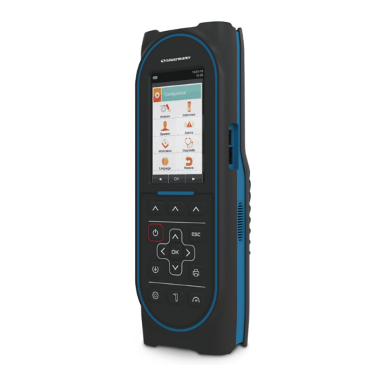
- Page 1 USER MANUAL Si-CA 320 FLUE GAS ANALYZER www.sauermanngroup.com...
-
Page 2: Foreword
About the Sauermann Group: For more than 40 years, the Sauermann Group has designed, manufactured and marketed products and services for the HVACR and industrial markets, focusing on the detection, measurement and control of indoor air quality (IAQ). We operate under three main brands: •... -
Page 3: Table Of Contents
Table of Contents FOREWORD ..........................2 IMPORTANT INFORMATION ...................... 6 Information about this manual ......................... 6 Safety information ........................... 6 SAFETY ............................. 7 Safety verification ............................ 7 Correct use of the product ........................7 Non-authorised use of the product ......................7 Precautions to be taken when using the Li-Ion battery pack .............. - Page 4 Configuration → Instrument → CO dilutor ..................38 9.2.5 Configuration → Instrument → Micromanometer ................39 9.2.6 Configuration → Operator ........................40 Configuration → Alarms ........................42 Configuration → Information ......................... 43 Configuration → Information → Battery.................... 44 9.5.1 9.5.2 Configuration→Information→Sensors ....................
- Page 5 Measurements → Temperature ....................... 107 13.0 Measurements → Pressure ......................108 13.5 Measurements → Tightness test ...................... 109 13.6 13.6.1 Connecting the leak test kit to the instrument .................. 109 13.7 Measurements→ Search for leak ..................... 110 13.7.1 Connection of probe for gas leak ..................... 110 13.7.2 Performing the test ..........................
-
Page 6: Important Information
2.1 Information about this manual This manual describes the operation, features and maintenance of the Si-CA 320 Flue gas analyzer. Read this instruction and maintenance manual before using the instrument. The operator must have a full understanding of the manual and follow the instructions within. -
Page 7: Safety
3.3 Non-authorised use of the product Use of the Si-CA 320 in areas of application other than those mentioned in the chapter 3.2"Correct use of the product" is the sole responsibility of the operator and the manufacturer assumes no responsibility for any loss, damage or costs that may result therefrom. It is recommended to read and pay attention to the instructions in this user and instruction manual. -
Page 8: Working Principle
4 WORKING PRINCIPLE 4.1 Working principle The Si-CA 320 is a portable analyser for combustion and emissions analysis. The device is equipped with: • A pneumatic circuit that can contain up to 6 sensors • An intuitive user interface allowing the device to be used without the operating instructions •... -
Page 9: Product Description
Designed for the eleven main fuel types such as natural gas, LPG, diesel and fuel oil, the Si-CA 320 also allows 16 other fuels of known chemical composition to be added to the memory. Saving and averaging the acquired data, printing the results (on a plain paper roll) and connecting to the computer for data storage via USB connection, are all features of the Si-CA 320. - Page 10 If there is an automatic autozero solenoid valve, the unit automatically performs a purging cycle and stops when the sensor returns to a value close to zero. Sauermann certifies the accuracy of the measurements only under cover of a calibration certificate issued by its laboratories or by another approved laboratory.
- Page 11 7 or higher operating system, once the specific Si-CA PCSoft software supplied with the instrument has been installed. ® Bluetooth connection (optional) The Si-CA 320 analyser is equipped with an internal Bluetooth module, which allows remote communication with the following devices: ® • Remote Bluetooth printer ®...
-
Page 12: Description Of The Components Of The Flue Gas Analyzer
5.3 Description of the components of the Flue gas analyzer Keyboard Gas exhaust Display screen P- connector (negative input for draught measurement) USB type B port for connection to power supply or for IN connector (input for the smoke sensor through the connection to a PC condensation separator unit) Mini Din port for connecting accessory probes by cable... -
Page 13: Keyboard
5.3.1 Keyboard Polyester adhesive keypad with preformed keys for principal control functions: KEYS FUNCTION KEYS FUNCTION Enables the displayed Access the printing menu interactive functions. Turns the device on/off Access the Configuration menu Exit the current display Carry out a combustion analysis Select and/or modify Access the Measurement... -
Page 14: Printer
Backlighting: To turn off the backlight for the display, press the following keys at the same time To turn the backlight back on again, simply press any key except 5.3.3 Printer Thermal printing on thermal paper. Pressing the print key accesses the menu where, in addition to editing the report, it is possible to access different printing options and to manually advance the paper to facilitate the replacement of the paper roll. -
Page 15: Technical Features
6 TECHNICAL FEATURES 6.1 Technical Features Autozero: Automatic autozero cycle with probe NOT inserted in the stack. Dilution: Increases the measurement range of the CO sensor to 100,000 ppm (10.00%). Programmable to provide simple protection of the CO sensor by intervening when the threshold is reached. -
Page 16: Measurement And Accuracy Ranges
6.2 Measurement and accuracy ranges MEASUREMENT MEASURING MEASUREMENT RESOLUTION DETAIL COMPONENT RANGE Electrochemical sensor 0 to 25.0% vol 0.1% vol ±0.2% vol ±10 ppm 0 to 200 ppm Electrochemical sensor 0 to 8000 ppm 1 ppm ±5% measured value 201 to 2000 ppm with H compensation ±10% measured value... -
Page 17: Using The Flue Gas Analyser
Remove the analyser from the packaging used for shipping and perform an initial check of it. Check the contents match the order specification. If you notice any signs of anomalies or damage, report the details as soon as possible to Sauermann or their representative agent and keep the original packaging. -
Page 18: Instrument Power Supply
If the battery life is too short, carry out a complete discharge of the battery followed by a complete 100% recharge cycle by supplying power to the instrument for 3 hours. If the problem persists, replace the battery with an original Sauermann battery or contact the SERVICE CENTRE for repair. -
Page 19: Connection Diagram
7.5 Connection diagram Water trap Ionisation with particle current probe filter Micro- Pressure Combustion manometer air sensor Combustion sensor... - Page 20 Power supply/battery charger Combustion probe for industrial engines...
-
Page 21: Power On - Off
8 POWER ON - OFF 8.1 Starting the device 15/01/14 15/01/14 10:00 10:00 Combustion analysis Combustion analysis λ,n 1.25 λ,n 1.25 T flue 190.1 90.1 °C °C T air 15.4 T air 15.4 °C °C ΔT 74.7 ΔT 74.7 °C °C Maintain the pressure for several seconds... -
Page 22: Configuration Menu
9 CONFIGURATION MENU 15/01/14 FUNCTION 10:00 Configuration Enables the displayed interactive operations. Return to the previous page. Analysis Instrument CONTEXT KEY FUNCTION Operator Alarms ◄ Select the available parameters. Information Diagnostic Enter the selected parameter. Language Restore ► Select the available parameters. PARAMETER DESCRIPTION SEE CHAPTER... -
Page 23: Configuration → Analysis
9.1 Configuration → Analysis FUNCTION 15/01/14 10:00 Enables the displayed interactive operations. Analysis configuration Return to the previous page. Fuel Condensation Fuel CONTEXT KEY FUNCTION O2 reference Reference O /NO report ◄ Select the available parameters. Autozero Measure units Enter the selected parameter. Measures list Air temp. -
Page 24: Configuration → Analysis → Fuel
9.1.1 Configuration → Analysis → Fuel 15/01/14 15/01/14 10:00 10:00 Configuration Configuration Fuel Fuel Natural gas Pellets – 8% Wood – 20% propane Woodchips Butane Coal Domestic fuel CO Off gas Heavy fuel oil Olive stones Rice husks Propane air Biogaz FUNCTION Enables the displayed interactive operations. -
Page 25: Configuration → Analysis → Condensation
9.1.2 Configuration → Analysis → Condensation 15/01/14 10:00 Configuration Condensation Altitude Sea level altitude Air R.H. Relative humidity of air FUNCTION Enables the displayed interactive operations. The arrows select each displayed line (the selected line is highlighted in red). In edit mode, scrolls through the possible values. Enters the edit mode of the selected data and then saves the change made. -
Page 26: Configuration → Analysis → Reference O
9.1.3 Configuration → Analysis → Reference O 15/01/14 10:00 Configuration reference Percentage of Oxygen per CO measurement Percentage of Oxygen per NO measurement Percentage of oxygen per So measurement FUNCTION Enables the displayed interactive operations. The "▲" and "▼" arrows select in turn the displayed lines (the selected line is highlighted in red). -
Page 27: Configuration → Analysis→ No /No Ratio
9.1.4 Configuration → Analysis→ NO /NO ratio 15/01/14 10:00 Configuration /NO ratio 1.05 FUNCTION Enables the displayed interactive operations. In edit mode, define the desired value. Enters edit mode then saves the change made. Pressing it in edit mode cancels the choice made, or returns to the previous page. CONTEXT KEY FUNCTION Enter edit mode. -
Page 28: Configuration → Analysis → Measure Units
9.1.5 Configuration → Analysis → Measure units 15/01/14 10:00 Configuration Measure units The selectable measure units are : ppm - mg/m - mg/kWh - g/GJ - g/m - g/kWh - % The selectable units of measurement are : ppm - mg/m - mg/kWh - g/GJ - g/m - g/kWh - % The selectable Measure units are: ppm - mg/m... -
Page 29: Configuration → Analysis → Autozero
9.1.6 Configuration → Analysis → Autozero 15/01/14 10:00 Configuration Autozero Duration of the autozero in seconds. Autozero Duration of the purging cycle in seconds. Purging FUNCTION Enables the displayed interactive operations. In edit mode, define the desired value. Enters edit mode then saves the change made. Pressing it in edit mode cancels the choice made, or returns to the previous page. -
Page 30: Configuration → Analysis → Measures List
9.1.7 Configuration → Analysis → Measures list 15/01/14 10:00 Configuration Measures list λ,n T flue T air ΔT Qs (PCI) ηs (PCI) “ FUNCTION Enables the displayed interactive operations. One at a time, select each displayed line (the selected line is highlighted in red). In edit mode, set the desired value Pressing it in edit mode cancels the choice made, or returns to the previous page. - Page 31 → Example: 1. Add a measurement to the list - example 15/01/14 15/01/14 15/01/14 15/01/14 10:00 10:00 10:00 10:00 Configuration Configuration Configuration Configuration Measures list Measures list Measures list Measures list λ,n λ,n ▲ λ,n T flue T flue λ,n T air T flue T air...
-
Page 32: Configuration → Analysis → Air Temperature
9.1.8 Configuration → Analysis → Air temperature 15/01/14 10:00 Configuration Air temperature Probe T °C Air T °C FUNCTION Enables the displayed interactive operations. In edit mode, set the desired value Also activates the displayed interactive functions. Return to the previous page. CONTEXT KEY FUNCTION Enters the modification mode of the Air T parameter: you can enter the value chosen... -
Page 33: Configuration→ Instrument
9.2 Configuration→ Instrument FUNCTION Enables the displayed interactive operations. Return to the previous page. Time/Date CONTEXT KEY FUNCTION Brightness Pump ◄ Select the available parameters. CO dilutor Micromanometer Enter in the selected parameter ► Select the available parameters. PARAMETER DESCRIPTION In this sub-menu you can activate or deactivate the wireless communication of the instrument with a PC, smartphone or tablet via Bluetooth ®... -
Page 34: Configuration → Instrument → Bluetooth
9.2.1 Configuration → Instrument → Bluetooth ® 15/01/14 10:00 Configuration Bluetooth Activate/deactivate Bluetooth Status ® Name of instrument Si-CA 120 MAC address detected 0026BB5500 FUNCTION Enables the displayed interactive operations. Also activates the displayed interactive functions. Return to the previous page. CONTEXT KEY FUNCTION Activate Bluetooth communication. -
Page 35: Configuration → Instrument → Time/Date
9.2.2 Configuration → Instrument → Time/Date 15/01/14 10:00 Time/Date configuration Time 14:00 Time, displayed in the selected format 15/01/14 Date Date, displayed in the selected format Mode Date format: EU (European) or USA (American) Mode Time format : 24h or 12h FUNCTION Enables the displayed interactive operations. -
Page 36: Configuration → Instrument → Brightness
9.2.3 Configuration → Instrument → Brightness 15/01/14 10:00 Brightness configuration FUNCTION Enables the displayed interactive operations. Increases or decreases the brightness of the screen. Saves the change made. Pressing it in edit mode cancels the choice made, or otherwise returns to the previous page. -
Page 37: Configuration → Instrument → Pump
9.2.4 Configuration → Instrument → Pump 15/01/14 10:00 Pump configuration Pump Flow Display of pump range, expressed in litres/minute. l/min FUNCTION Enables the displayed interactive operations. In edit mode, set the desired value Enters edit mode and then saves the change made. Pressing it in edit mode cancels the choice made, or returns to the previous page. -
Page 38: Configuration → Instrument → Co Dilutor
9.2.5 Configuration → Instrument → CO dilutor 15/01/14 10:00 Configuration CO dilutor Available settings: auto, on or off Mode auto Threshold 4000 Threshold that activates the dilution pump (available only if the "Mode" parameter is set to "auto") FUNCTION Enables the displayed interactive operations. In edit mode, set the desired value Enters edit mode and then saves the change made. -
Page 39: Configuration → Instrument → Micromanometer
9.2.6 Configuration → Instrument → Micromanometer 15/01/14 10:00 Micromanometer configuration Socket Sets the input used to perform the test: P+ or P- FUNCTION Enables the displayed interactive operations. In edit mode, set the desired value Enters edit mode and then saves the change made. Pressing it in edit mode cancels the choice made, or returns to the previous page. -
Page 40: Configuration → Operator
9.3 Configuration → Operator 15/01/14 10:00 Configuration Operator Operator 1 Operator 2 Operator 3 Operator 4 Operator 5 Operator 6 Operator 7 Operator 8 FUNCTION Enables the displayed interactive operations. In "edit text": move the cursor to the box corresponding to the letter or number to be added to form the required word. - Page 41 → Example: 1. Edit text 15/01/14 15/01/14 15/01/14 10:00 10:00 10:00 Configuration Edit text Edit text Operator Operator 1 Operator 2 Operator 1_ Operator_ Operator 3 Operator 4 Operator 5 Operator 6 1 2 3 4 5 6 7 8 9 0 1 2 3 4 5 6 7 8 9 0 A B C D E F G H I J A B C D E F G H I J...
-
Page 42: Configuration → Alarms
9.4 Configuration → Alarms 25/09/18 25/09/18 10:00 Alarms Number Identification number of the configured alarm Parameter observed: O - CO - NO - NO2 - P diff - Plow - P ext - T1 - Measure T2 Alarm type configured: maximum - minimum - off Mode maximum Threshold for the previously configured alarm type: ±99999999.999... -
Page 43: Configuration → Information
9.5 Configuration → Information 15/01/14 FUNCTION 10:00 Enables the displayed interactive operations. Information Return to the previous page. Battery Sensors Reminder Info Service CONTEXT KEY FUNCTION ◄ Select the available parameters. Probe Enter in the selected parameter ► Select the available parameters. PARAMETER DESCRIPTION Displays the state of charge of the internal battery. -
Page 44: Configuration → Information → Battery
9.5.1 Configuration → Information → Battery 15/01/14 10:00 Information Battery FUNCTION Enables the displayed interactive operations. Return to the previous page. CONTEXT KEY FUNCTION Return to the previous page. -
Page 45: Configuration→Information→Sensors
9.5.2 Configuration→Information→Sensors 15/01/14 15/01/14 25/09/18 10:00 10:00 10:00 Information Sensors Sensors S1: O S2: CO For further information, see Chapter 9.6.1. S3: NO CO S2 S4: NO S3 NO FUNCTION Enables the displayed interactive operations. Return to the previous page. CONTEXT KEY FUNCTION Displays details about the main characteristics of the installed sensors. -
Page 46: Configuration→Information→Info Service
9.5.3 Configuration→Information→Info Service 15/01/14 15/01/14 15/01/14 10:00 10:00 10:00 Information Information Information Service Service Service Sauermann. Rue Koufra Model Si-CA 320 Bootloader version 1.02 24700 Montpon Serial number 9999 Protocol number 000001 Tel. 05 53 80 85 00 0x2765 Firmware version 9.99... -
Page 47: Configuration→Information→Reminder
9.5.4 Configuration→Information→Reminder 15/01/14 10:00 Password Reminder 0 0 0 FUNCTION Enables the displayed interactive operations. Define password The password is: 1111. Return to the previous page. CONTEXT KEY FUNCTION Confirms the password entered and accesses the Reminder menu. Return to the previous page. Displays information about the help desk. -
Page 48: Configuration→Information→Probe
9.5.5 Configuration→Information→Probe 15/01/14 10:00 Information Probes Micromanometer int. 1039 External probe ---- FUNCTION Enables the displayed interactive operations. Return to the previous page. CONTEXT KEY FUNCTION Return to the previous page. -
Page 49: Configuration→Diagnostic
9.6 Configuration→Diagnostic 15/01/14 FUNCTION 10:00 Diagnostic Enables the displayed interactive operations. Return to the previous page. Sensors Gas probe Hardware Pump CONTEXT KEY FUNCTION ◄ Select the available parameters. On-site cal. Enter in the selected parameter ► Select the available parameters. PARAMETER DESCRIPTION Displays information on the state and calibration of the electrochemical sensors:... -
Page 50: Configuration→Diagnostic→Sensors
9.6.1 Configuration→Diagnostic→Sensors 15/01/14 10:00 Diagnostic sensors S1: O S2: CO S3: NO S4: NO FUNCTION Enables the displayed interactive operations. Select the fuel. Also activates the interactive function visible on the left side of the screen. Return to the previous page. CONTEXT KEY FUNCTION Display details for the selected sensor (see the example as reported below). -
Page 51: Configuration→Diagnostic→Gas Probe
9.6.2 Configuration→Diagnostic→Gas probe 15/01/14 10:00 Connect the gas probe equipped with the filter unit to the Instrument. Fully insert the probe Diagnostics tip into the black cap provided with the Instrument as shown in the figure below: Gas probe Close the flue gas probe Press OK to start Black rubber cap (provided) -
Page 52: Configuration→Diagnostic→Hardware
9.6.3 Configuration→Diagnostic→Hardware 15/01/14 10:00 Diagnostic Hardware Memories Status of memory Calibration Calibration status HW Cpu version CPU board version HW MB version Version of motherboard FUNCTION Enables the displayed interactive operations. Return to the previous page. CONTEXT KEY FUNCTION Return to the previous page. -
Page 53: Configuration→Diagnostic→Pump
9.6.4 Configuration→Diagnostic→Pump 15/01/14 10:00 Diagnostic pump Pump Flow l/min FUNCTION Enables the displayed interactive operations. In edit mode, it changes from on to off. Enters edit mode and then saves the change made. Return to the previous page. CONTEXT KEY FUNCTION Enter modification mode: the gas suction pump can be switched on/off. -
Page 54: Configuration→Diagnostic→On Site Cal
9.6.5 Configuration→Diagnostic→On site cal. 15/01/14 10:00 Password On site cal. 0 0 0 FUNCTION Enables the displayed interactive operations. Define password Selects a line; the selected line is highlighted in red. In modification sets the selected value or mode. Also activates the interactive function visible on the left side of the screen. Return to the previous page. - Page 55 → Calibration procedure Here are the instrument and devices that are required to perform the calibration: - Gas cylinder adapted to the sensor in question, equipped with a pressure regulator CAUTION: For on-site calibration of the O sensor, the zero calibration value must be performed with nitrogen or any other gas mixture that does NOT contain oxygen.
- Page 56 → 3. In the on-site calibration menu, the list of installed adjustable sensors is displayed. On the "Calibration" screen, information about the last calibration and its values is displayed. Calibrate: saves a new calibration. 15/01/14 15/01/14 10:00 10:00 Status: Not active: returns to factory calibration.
- Page 57 → Calibration example for the O sensor: Calibration will only be possible if the sensor status is set to" ----" (cell that has never had an on-site calibration) or • "inactive". 15/01/14 15/01/14 15/01/14 10:00 10:00 10:00 Onsite calibration Onsite calibration Onsite calibration sensor sensor...
- Page 58 → Once the stabilisation period has elapsed, select the "Calibrate" line and activate the function to store the new calibration. • Calibration example for a toxic gas (CO) sensor: 15/01/14 15/01/14 Temporary notifications visible on the "Status" line: 10:00 10:00 Saving: records the calibration performed On site calibration On site calibration...
- Page 59 → Calibration will only be possible if the state is set to" ----" or" not active". • 15/01/14 15/01/14 15/01/14 10:00 10:00 10:00 On site calibration On site calibration On site calibration CO sensor CO sensor CO sensor Calibrate Calibrate Calibrate Status Status...
- Page 60 → Once the stabilisation period has elapsed, select the "Calibrate" line and activate the function to store the new calibration. • Messages in the 'Status' line: 25/09/18 25/09/18 10:00 10:00 Saving: the instrument is saving the performed calibration On site calibration On site calibration Error: the sensor is not adjusted for one of the following Sensor CO...
-
Page 61: Configuration → Language
9.7 Configuration → Language 15/01/14 10:00 Configuration Language English French FUNCTION Enables the displayed interactive operations. Scrolls through the available languages. Save the selected language Return to the previous page. CONTEXT KEY FUNCTION Save the selected language... -
Page 62: Configuration → Restore
9.8 Configuration → Restore 15/01/14 15/01/14 10:00 10:00 Configuration Configuration Restore Restore WARNING Clear memory data and Confirm restoring? restore factory F1: restore F2: cancel settings? FUNCTION Enables the displayed interactive operations. Starts the factory data recovery phase. Exits the displayed page without restoring factory data. CONTEXT KEY FUNCTION Starts the factory data recovery phase. -
Page 63: Memory
10 MEMORY 10.1 Memory Menu 15/01/14 FUNCTION 10:00 Enables the displayed interactive operations. Memory Return to the previous page. Save Average Select Data logger CONTEXT KEY FUNCTION ◄ Select the available parameters. Delete Usage % Enter in the selected parameter ►... - Page 64 Data logger (automatic mode) This mode is fully programmable by the user (it is necessary to programme the number of samples to be taken, the sampling time for each sample and the printing mode). When the Flue gas analysis begins, the instrument automatically executes and records the number of sample analyses programmed and sets the time between each of them according to the programmed time.
-
Page 65: Memory Organisations
10.2 Memory organisations... -
Page 66: Memory Menu → Save
10.3 Memory Menu → Save 15/01/14 15/01/14 10:00 10:00 Memory Memory Save Save Mode Mode manual Manual analysis mode Data logger Analysis mode Data logger Memory Memory Number of selected memory Selected memory number Analysis Samples Number of analyses carried out Number of samples to be taken Interval Interval between the samples... - Page 67 Example 1: Storing the Flue gas analysis in manual mode 15/01/14 15/01/14 15/01/14 10:00 10:00 10:00 Memory Memory Memory Save Save Save Mode Mode manual manual Mode manual Memory Memory Memory Analysis Analysis Analysis Example 2: Storing the Flue gas analysis in Data logger mode 25/09/18 25/09/18 25/09/18...
-
Page 68: Memory Menu → Average
10.4 Memory Menu → Average 15/01/14 10:00 Memory Average interval λ,n 1.25 T flue 190.1 °C T air 15.4 °C ΔT 74.7 °C ηs 91.4 FUNCTION Enables the displayed interactive operations. Scrolls through the values of the average analysis. Also activates the interactive function visible on the left side of the screen. Return to the previous page without saving the changes made. -
Page 69: Memory Menu → Select
10:00 Memory Memory Select Select Number of memory slot Memory Boiler Boiler model xxxx Customer Customer Address Sauermann Customer address Address of Address Rue Koufra customer BP16 Montpon Telephone Telephone number Telephone Number Telephone 05 53 80 85 00 Boiler model... -
Page 70: Memory → Recall Memory
15/01/14 10:00 10:00 Memory Memory Select Recall Memory Measure conditions Single analysis Customer Sauermann Address Average analysis Rue Pierre Paul Paris Telephone 0424 567842 Boiler xxxx FUNCTION Enables the displayed interactive operations. Selects a line; the selected line is highlighted in red. - Page 71 2. “Single analysis” details 15/01/14 15/01/14 10:00 10:00 Memory Memory Single analysis Average analysis 15/01/14 15:10:30 15/01/14 15:15:00 λ,n 15/01/14 15:20:30 1.25 T flue 15/01/14 15:25:00 190.1 °C T air 15/01/14 15:30:35 15.4 °C ΔT 74.7 °C ηs 91.4 ▲ FUNCTION Enables the displayed interactive operations.
- Page 72 3. Average interval details 15/01/14 15/01/14 10:00 10:00 Memory Memory Average Average analysis Refers to the sample number from which to calculate the average analysis. Refers to the sample number from which to start (inclusive) to λ,n calculate the average analysis. 1.25 T flue 190.1...
-
Page 73: Memory: Recall The "Maintenance Certification" Memory
10.5.2 Memory: Recall the "Maintenance Certification" memory 15/01/14 15/01/14 10:00 10:00 Memory Memory Select Analysis list Memory 15/01/14 15:10:30 Customer KIMO 15/01/14 15:15:00 Address Rue Koufra 15/01/14 15:20:30 24700 Montpon 15/01/14 15:25:00 15/01/14 15:30:35 Telephone 0553808500 Boiler xxxx Date 15/01/14 ▲... - Page 74 2. Analysis list details 15/01/14 15/01/14 10:00 10:00 Memory Memory Recall Analysis list Measure conditions Single analysis T flue 190.1 °C T air 15.4 °C ηt 91.4 FUNCTION Enables the displayed interactive operations. Selects a line; the selected line is highlighted in red. In detail display, switches to the display of the next or previous page.
-
Page 75: Memory Menu → Data Logger
10.6 Memory menu → Data logger 15/01/14 10:00 Memory The selectable analysis modes are: Data logger manual - data log - maintenance certification. Mode UNI 10389 Samples Number of samples to be performed (parameter not visible in manual analysis mode). Time period Time required to take each sample (parameter not visible in manual analysis mode). -
Page 76: Memory → Delete
10.7 Memory → Delete 15/01/14 FUNCTION 10:00 Memory Enables the displayed interactive operations. Delete Return to the previous page. Single CONTEXT KEY FUNCTION ◄ Select the available parameters. Enter in the selected parameter ► Select the available parameters. PARAMETER DESCRIPTION This option allows you to delete the contents of each of the memories. -
Page 77: Memory → Delete → Single
Memory Delete following message: single single Memory Memory Number of the memory Customer WARNING Customer Sauermann Sauermann Address 850 Town Center Dr Address Zone industrielle 24700 Customer address Confirm deleting? WARNING Langhorme, PA 19047 Montpon F1: Delete Confirm deleting all data? -
Page 78: Memory → Delete → All
10.7.2 Memory → Delete → All 15/01/14 15/01/14 10:00 10:00 Memory Memory Delete all Delete all WARNING Delete all data? Confirm deleting? F1: delete F2: cancel FUNCTION Enables the displayed interactive operations. Starts the deletion phase of all memory slots. Return to the previous page. -
Page 79: Memory → Usage
10.8 Memory → Usage % 15/01/14 10:00 Memory Usage % FUNCTION Enables the displayed interactive operations. Return to the previous page. CONTEXT KEY FUNCTION Return to the previous page. -
Page 80: Print
11 PRINT 11.1 Print FUNCTION 21/03/18 10:00 Enables the displayed interactive operations. Print Return to the previous page. Report Printer CONTEXT KEY FUNCTION Measures list Header ◄ Selects available parameters Enter the selected parameter ► Selects available parameters PARAMETER DESCRIPTION Allows the results of the Flue gas analysis to be printed on a report that confirms the execution of the measurement. -
Page 81: Print → Report
11.2 Print → Report 15/01/14 15/01/14 10:00 10:00 Print Print Report Report Analysis running Analysis running Copies WARNING Model partial Printing Please wait... ٪ Time/Date auto Ttim auto ηc ٪ ηt 91.4 F1: stop 148 ppm 40 ppm NOX/NO: 1.03 41 ppm CO amb. -
Page 82: Print → Configuration
11.3 Print → Configuration 15/01/14 10:00 Print Configuration Copies Programming the number of copies to be printed: 1 to 5. Report partial Selectable report models: partial - complete - total Time/Date auto Toggle between: Manual: the date and time are not printed on the analysis report. Auto: date and time are automatically printed on the analysis report. -
Page 83: Print → Pairing
11.3.1 Print → Pairing 15/01/14 10:00 Print Pairing WARNING Turn on the printer and start searching F1: search F2: esc FUNCTION Enables the displayed interactive operations. Selects a line; the selected line is highlighted in red. In edit mode, set the desired value or mode. Also activates the interactive function visible on the left side of the screen. - Page 84 1. Once the Bluetooth printer configured, follow the instructions below: ® 15/01/14 15/01/14 10:00 10:00 Print Print Pairing Pairing MPT-II WARNING Turn on the printer and start searching F1: search F2: esc 2. Select the line corresponding to the Bluetooth printer to be paired, and proceed as follows: ®...
-
Page 85: Print → Printer
11.4 Print → Printer 15/01/14 10:00 Print Printer Selectable printer type: Bluetooth Type Bluetooth (external) ® ---- Name of Bluetooth printer paired with the instrument. ® ---- Address of the Bluetooth printer paired with the instrument. ® FUNCTION Enables the displayed interactive operations. Selects a line;... -
Page 86: Print → Header
11.5 Print → Header 15/01/14 10:00 Print Header ---- Line1 ---- Line2 ---- Line3 ---- Line4 ---- Line5 ---- Line6 FUNCTION Enables the displayed interactive operations. In "edit text": moves the cursor to the box corresponding to the letter or number chosen to create the requested word. - Page 87 Example: 1. Edit text 15/01/14 15/01/14 15/01/14 10:00 10:00 10:00 Print Edit text Edit text Header Line1 ---- Line2 ---- Line3 ---- Operator 1_ Operator 1_ Line4 ---- Line5 ---- Line6 ---- 1 2 3 4 5 6 7 8 9 0 1 2 3 4 5 6 7 8 9 0 A B C D E F G H I J A B C D E F G H I J...
-
Page 88: Print → Measures List
11.6 Print → Measures list 15/01/14 10:00 Print Measures list λ,n T flue T air ΔT Qs (PCI) ηs (PCI) “ FUNCTION Enables the displayed interactive operations. Selects the available measurements from the proposed list. In edit mode, scrolls through the measurements. Confirms the change that has been made. - Page 89 Example: 1. Add a measurement to the list 15/01/14 15/01/14 15/01/14 15/01/14 10:00 10:00 10:00 10:00 Configuration Configuration Configuration Configuration Measures list Measures list Measures list Measures list ▼ λ,n λ,n λ,n T flue T flue Tsmoke λ,n ▲ T air T air T air T flue...
-
Page 90: Flue Gas Analysis
12 FLUE GAS ANALYSIS 12.1 FLUE GAS ANALYSIS To perform the complete flue gas analysis, proceed as follows. SOME IMPORTANT WARNINGS TO CONSIDER DURING THE COMBUSTION ANALYSIS ARE LISTED BELOW: FOR A CORRECT ANALYSIS NO AIR MUST FLOW INTO THE PIPE FROM OUTSIDE DUE TO A BAD TIGHTENING OF THE CONE OR A LEAK IN THE PIPELINE. -
Page 91: Simultaneous Measurement Of Pressure, O , Pollutants
The correct point of introduction of the probe into the chimney is the point corresponding to a distance from the boiler of twice the diameter of the flue gas nozzle or, if this is not possible, in accordance with the instructions of the boiler manufacturer. To position the probe, it is necessary to make a hole of about 13/16 mm (if there isn’t one already) in the flue gas duct and screw in the positioning cone supplied with the probe so as to provide a good support for when it is introduced, thus avoiding taking air from the outside. -
Page 92: Flue Gas Analysis - Preliminary Operations
12.2 Flue gas analysis - preliminary operations 15/01/14 10:00 Combustion analysis Do not insert the gas sample probe in the chimney: λ,n 1.25 °C Pressure for T air 15.4 several °C ΔT 74.7 seconds °C ηs 91.4 15/01/14 15/01/14 10:00 10:00 Combustion analysis Memory... - Page 93 15/01/14 10:00 Print PARAMETERS TO BE SET BEFORE CONTINUING Report Configuration (see chapter 11): Configuration Test Header Header Measures list Measures list Printing 25/09/18 10:00 ENTER THE FOLLOWING MEASUREMENTS BEFORE CONTINUING THE COMBUSTION Measurements ANALYSIS Smoke Temperature Otherwise, the measurements will not be printed on the analysis report.
-
Page 94: Flue Gas Analysis - Certification Mode
12.3 Flue gas analysis - certification mode First, select the "Maintenance certification" mode Press the key and select Data logger Memory Memory Mode Mode Save Usage % Memory Memory Memory Mode Mode Mode Then select the memory in which you want to save your certification by pressing the key again and selecting "Select". - Page 95 Once the "Maintenance Certificate" mode and memory have been selected, press , then press key located below “AdE”. Measurement Combustion analysis Confirmation of entry Ambient CO 190.1 Draft Combustion analysis 15.4 Use the arrows to select the measurement you want to perform. Measurements can be made in any order you wish. However, for a correct measurement, it is preferable to carry out them in the order indicated.
-
Page 96: Execution Of Flue Gas Analysis - Data Logger Mode
12.4 Execution of Flue gas analysis - data logger mode 15/01/14 15/01/14 10:00 10:00 Memory Combustion analysis Save Mode data logger Memory λ,n Samples 1.25 T flue Time periods 190.1 °C T air 15.4 °C ΔT 74.7 °C ηs 91.4 04/03/16 04/03/16 10:00... - Page 97 04/03/16 10:00 Print Report Memory Analysis average WARNING Model partial Printing. Please wait... auto NOTE: If automatic printing is selected when the analysis is programmed, the Instrument will automatically start printing the average analysis. If, on the other hand, manual printing has been chosen (as in the example), after entering the third analysis, the average analysis is displayed and can be printed or downloaded according to the following procedure: 15/01/14...
-
Page 98: Execution Of Flue Gas Analysis-Manual Mode
12.5 Execution of flue gas analysis—manual mode 15/01/14 15/01/14 15/01/14 10:00 10:00 10:00 Memory Combustion analysis Combustion analysis Save Mode manual Memory λ,n λ,n Analysis 1.25 1.25 T flue T flue 190.1 190.1 °C Saves °C T air T air 15.4 15.4 analysis... - Page 99 15/01/14 15/01/14 15/01/14 10:00 10:00 10:00 Print Memory Print Report Average analysis Report Memory Memory Analysis average CAUTION Analysis Average Model partial λ,n Printing. 1.25 Model partial Please wait... T flue 190.1 F1: stop °C T air 15.4 °C ΔT 74.7 °C ηs...
-
Page 100: End Of Analysis
12.6 End of Analysis - At the end of the Flue gas analysis, disconnect carefully the sample probe and any combustion air probe from the respective ducts, taking care to avoid contact burns. - Then switch off the instrument with the On/Off button. If the instrument detects the presence of a high level of CO or NO, a purging cycle is performed during which the pump draws in clean air until concentrations are partial. - Page 101 Maintenance of water trap/filter unit AFTER EACH ANALYSIS, CHECK FOR ANY PRESENCE OF WATER IN THE CONDENSATE COLLECTION BOWL AND ELIMINATE IT, IF ANY. PUT THE PROBE BACK IN THE CASE ONLY AFTER YOU HAVE ELIMINATED CONDENSATE FROM THE TUBE AND THE EXPANSION TANK (SEE CHAPTER 'MAINTENANCE'). REPLACE THE FINE DUST FILTER IF IT IS VISIBLY DIRTY OR WET (SEE CHAPTER 'MAINTENANCE').
-
Page 102: Measurements
13 MEASUREMENTS 13.1 MEASUREMENTS 15/01/14 FUNCTION 10:00 Enables the displayed interactive operations. Measur Return to the previous page. Draft Smoke Ambient CO Temperature The "Draft" and "Ambient CO" icons are not available in the menu Pressure Tightness test in "Maintenance certification" mode. Aux. - Page 103 PARAMETER DESCRIPTION This menu is used to measure the temperature of the sending water and/or the return water using a thermocouple K contact probe connected to input T1 (OPTIONAL). Then, by the function Δ T it is possible to calculate the relative temperature difference between the two Temperature measurements.
-
Page 104: Measurements → Draft
13.2 Measurements → Draft 04/03/16 04/03/16 04/03/16 10:00 10:00 10:00 Measurement Measurement Measurement Draft UNI 10845 Draft UNI 10845 Draft UNI 10845 P+ ext P+ low P diff T outdoor T outdoor T outdoor °C °C °C P diff ref. P diff ref. -
Page 105: Measurements → Smoke
13.3 Measurements → Smoke 15/01/14 10:00 Measurement Smoke Measure 1 Measure 2 Measure 3 Average - Perform opacity index measurements using the optional kit. - Enter the values that have been measured. - The opacity values to be recorded must be entered before the analyses are recorded. - To attach the opacity values to the current analysis, activate the Memory function - To print the report with the opacity index measurement, activate the function ‘... -
Page 106: Measurements → Ambient Co
13.4 Measurements → Ambient CO 15/01/14 10:00 Measurement Ambient CO CO max It is mandatory to carry out a reset in clean air for the ambient CO measurement to be correct. To do this, turn on the Instrument and wait outside of the room where the test is to be performed until the reset is complete. - The ambient CO values to be recorded must be entered before the analyses are recorded. -
Page 107: Measurements → Temperature
13.0 Measurements → Temperature 15/01/14 15/01/14 10:00 10:00 Measurement Measurement Temperature Temperature T1 flow T1 flow 70.5 °C ΔT T2 return 45.2 °C °C ΔT 25.3 °C ΔT FUNCTION Enables the displayed interactive operations. Return to the previous page. Generates and displays a QR code on the screen to download the data of the selected analysis that is visible on the screen. -
Page 108: Measurements → Pressure
13.5 Measurements → Pressure 15/01/14 15/01/14 10:00 10:00 Measurement Measurement Pressure Pressure Differential pressure Pressure measurement P diff P ext measurement by the using the external internal pressure pressure gauge. 0.01 0.01 sensor. FUNCTION Enables the displayed interactive operations. Return to the previous page. Generates and displays a QR code on the screen to download the data of the selected analysis that is visible on the screen. -
Page 109: Measurements → Tightness Test
13.6 Measurements → Tightness test 15/01/14 FUNCTION 10:00 Enables the displayed interactive operations. Tightness test Return to the previous page. Existing Result CONTEXT KEY FUNCTION ◄ Select the available parameters. Enter in the selected parameter ► Select the available parameters. PARAMETER DESCRIPTION In this menu it is possible to perform the leak test on new or refurbished systems, once repair work has been carried... -
Page 110: Measurements→ Search For Leak
13.7 Measurements→ Search for leak 15/01/14 FUNCTION 10:00 Measurements Enables the displayed interactive operations. Leak detector Return to the previous page. CONTEXT KEY FUNCTION Perform a measurement reset. 13.7.1 Connection of probe for gas leak - Connect the probe connection to the IN input of the instrument. 13.7.2 Performing the test At the end of the autozero cycle, perform a measurement autozero and proceed with the test. -
Page 111: Measurements → Measurements Appendices
13.8 Measurements → Measurements Appendices FUNCTION Enables the displayed interactive operations. Return to the previous page. Velocity Power of burner CONTEXT KEY FUNCTION ◄ Select the available parameters. Enter in the selected parameter ► Select the available parameters. PARAMETER DESCRIPTION With the help of a Pitot tube and a K thermocouple, the instrument can also measure the velocity of a gas (air/fumes). -
Page 112: Measurements→Velocity
13.9 Measurements→Velocity 15/01/14 10:00 Pitot Configuration Measurement : air or flue gas. Altitude Altitude based on sea level. Measure units selectable between m/s, km/h, fpm, mph. Unit Enter the Pitot tube K factor declared by the tube manufacturer. K Pitot 1.001 Temperature recording mode: Probe T... -
Page 113: Connection Of Pitot Tube To Instrument
13.9.1 Connection of Pitot tube to instrument - Connect the Pitot tube (accessory) to the two inputs P + and P- which are normally used for differential pressure measurement - Connect the cable relating to the thermocouple K of the smoke sensor to the T1 connector of the instrument. If using a Pitot tube with Tc-K thermocouple, connect the connector to the T1 input of the instrument. -
Page 114: Test Execution
Rue Koufra 10:30 Tel. 01 23 45 67 89 21/03/18 Oper.: Mario Rossi 10:30 Signature: Print Report running Analysis Si-CA 320 Serial n.: 999989 Model WARNING Date: 12/01/15 Time: 10.30 Printing. Gas: Air Please wait. V air 9.11 km/h F1: stop Density 1.199 kg/m... -
Page 115: Measurements → Power Of Burner
13.10 Measurements → Power of burner The thermal capacity can be 15/01/14 15/01/14 10:00 10:00 calculated by entering a flow rate value or by reading the volumetric Power of Power of counter (only for gaseous fuels). burner burner Enter the value of the thermal power Mode manual measurement... -
Page 116: Testing In Manual Mode
13.10.1 Testing in manual mode 15/01/14 15/01/14 15/01/14 10:00 10:00 10:00 Power of burner Power of burner Power of burner Power of burner Power of burner Power of burner 10.74 00.00 00.00 15/01/14 10:00 Power of burner Power of burner 10.74... -
Page 117: Testing In Measure Mode (Based On Flow Rate)
13.10.2 Testing in measure mode (based on Flow rate) 15/01/14 15/01/14 15/01/14 10:00 10:00 10:00 Power of burner Power of burner Power of burner Configuration Power of burner Power of burner 0.00 0.00 Mode measurement Flow Flow 0.00 0.00 Type flow ... -
Page 118: Testing In Measure Mode (Based On Meter)
13.10.3 Testing in measure mode (based on meter) 25/09/18 25/09/18 25/09/18 10:00 10:00 10:00 Power of burner Power of burner Power of burner Configuration Power of burner Power of burner Mode measure 0.00 0.00 Wait time Wait time Type meter 00:02:00 00:01:57 ATTENTION... - Page 119 25/09/18 25/09/18 10:00 10:00 Power of burner Power of burner Power of burner Power of burner 0.56 0.56 Wait time 00:00:00 Wait time 00:00:00 Final volume Final volume Starting volume Starting volume...
-
Page 120: Measurements → Ionization Current
13.11 Measurements → Ionization current Measurements Ioniz. current FUNCTION Enables the displayed interactive operations. Selects a line; the selected line is highlighted in red. In edit mode, set the desired value. Also activates the interactive function visible on the left side of the screen. Return to the previous page. -
Page 121: Sensors
14 SENSORS 14.1 Position of sensors CELL POSITIONING INSIDE THE CELL COMPARTMENT GRAPHIC REPRESENTATION ON SCREEN 04/03/16 10:00 Sensors S1: O S2: CO+H2 S3: NO S4: SO S5: CO S6: H POSITION POSITION POSITION POSITION POSITION POSITION... -
Page 122: Sensor Type And Relevant Positioning
14.1 Sensor type and relevant positioning POSITION CODE 2 Flex Sensor CO+H Flex Sensor CO+H low range Flex Sensor Flex-Sensor CO 100,000 ppm Flex-Sensor CO 20,000 ppm ... -
Page 123: Life Of Gas Sensors
Sensor characteristics diminish as the reagents are consumed and when these have been used up completely the sensor must be replaced. The sensors must be recalibrated on a regular basis to assure measuring accuracy: recalibration can only be performed by a qualified Sauermann service centre. Chart 14.4 illustrates the characteristics inherent to each sensor. 14.3 Gas sensors life table... -
Page 124: Extension To 6 Sensors
14.4 Extension to 6 sensors The Si-CA 320 analyser can accommodate up to 6 sensors. It is easy for the user to add sensors, simply follow the procedure below: - The instrument can accept up to a maximum of 6 sensors. -
Page 125: Cxhy Sensor For Measuring Unburnt Hydrocarbons
14.5 CxHy sensor for measuring unburnt hydrocarbons Unburnt hydrocarbons are chemicals produced by incomplete combustion of molecules composed of carbon and hydrogen. They are usually known as HC or CxHy: when you replace "x" and "y" with the number of C and H atoms, the type of fuel oil is . -
Page 126: Maintenance
At least once a year, send the analyser to the SUPPORT CENTRE for careful internal inspection and cleaning. Highly qualified Sauermann personnel are always available for all types of commercial, technical, operating and maintenance information. The support centre is always willing to return the instrument to you as if it had only just been manufactured. Adjustments are made to gas... -
Page 127: Replacing The Gas Sensors
15.3 Replacing the gas sensors It is necessary to replace the gas sensors of the device periodically with new sensors or calibrated sensors (see following table). The replacement operation is easily carried out by the user by following the instructions below: Unscrew the two fixing screws on the cover of the sensor/battery compartment cover Remove the cover and access the sensor/battery compartment. - Page 128 Identify the position of the sensor to be replaced; below is an example of a sensor to be replaced with a connected electrical connection. Electrical connection Disconnect the electrical connection from the sensor to be replaced; below is an example of a sensor with a disconnected connection.
- Page 129 The sensor is fixed in its position by a bayonet fixing. To remove it, it must be rotated counter-clockwise; below is an example of a rotating sensor. When rotating the sensor, be careful not to exert pressure on the printed circuit board above: only exert pressure on the plastic surround.
- Page 130 Turn the sensor clockwise until the end of the end position is triggered (see point 4). When rotating the sensor, be careful not to exert pressure on the printed circuit board above: only exert pressure on the plastic surround. Reconnect the electrical connection (see point 3). Close the rear cover of the sensor compartment and tighten the two screws (see point 1).
-
Page 131: Replacing The Battery Pack
15.4 Replacing the battery pack To change the battery pack, proceed as illustrated below: Remove the battery compartment cover. Remove the battery pack. Disconnect the connector from the pack and replace the pack by following the steps described here in reverse. Battery pack connector... -
Page 132: Troubleshooting
16 TROUBLESHOOTING 16.1 Troubleshooting guide PROBLEM PROBABLE CAUSES AND POSSIBLE SOLUTIONS a. Keep the On/Off key depressed for at least 2 seconds. The instrument does not work at all. When the On/Off b. The battery is low; connect the battery charger to the instrument. pushbutton is pressed the instrument does not come on. - Page 133 Trouble shooting guide PROBLEM PROBABLE CAUSES AND POSSIBLE SOLUTIONS The rear lighting of the display is not on. The backlighting LED’s are faulty. Contact the nearest service centre to replace the display. a. Battery capacity is limited by low temperatures. To achieve a longer The batteries last less than 9 hours.
-
Page 134: Spare Parts And Servicing
Flex CO 0-50% VV sensor, pre-calibrated and interchangeable Flex H S sensor, pre-calibrated and interchangeable 17.2 Service To contact customer services: Sauermann Industrial Zone - BP16 24700 Montpon Tel. 05 53 80 85 00 Fax. 05 53 80 16 81... - Page 135 Enter a pre-defined email address. Select the data separation mode: coma (,) or semi colon (;). This setting is useful if you want to download the.csv file to an Excel spreadsheet or Google Drive. Displays the application version and Sauermann contacts.
-
Page 136: Example Of A File Exported As A .Csv And Imported Into An Excel File
Enter the email address if different from SI-CA 320 the predefined one Select one of the two data separation modes. Select the shared file format. Select the app to use when sending. 17.3 Example of a file exported as a .csv and imported into an Excel file... - Page 137 192/2005 and 23 ppm subsequent modifications 0.0 ٪ Ref. O and integrations CO ref 92 ppm 0.0 ٪ Ref. O Si-CA 320 NO ref 52 ppm N. series: 999989 0.0 ٪ Ref. O ref.: 56 ppm Memory: 01 Draft 4.5 Pa...
- Page 138 ηc 192/2005 and subsequent ٪ ηt 91.4 modifications and 148 ppm integrations NOX/NO: 1.03 41 ppm Si-CA 320 N. series: Amb. CO 0 ppm 999989 memory: 01 Analysis: Draft: 0.05 hPa average Date: T external: 20 °C T flue T 191.1 °C...
- Page 139 Rue Koufra Via Rossi, 9 Tel. 01 23 45 67 89 Tel.02/12345678 Oper.: Mario Rossi Oper.: Mario Rossi Signature Signature Verified in SI-CA 320 accordance with N. series: standard UNI 11137 999989 memory: 2012 Indirect method Date: 04/04/14 SI-CA 320 Time: 10.15...
- Page 140 APPENDIX C Coefficients of the fuels and Formulas The following table shows the coefficients of the saved fuels that will be used to calculate losses and efficiencies. Coefficients for calculating combustion efficiency Fuel CO2t M air V gas dry (KJ/Kg) (KJ/Kg) (Kg/Kg) (Kg/Kg)
-
Page 141: Advice For An Accurate Analysis
18 APPENDIX A 18.1 Advice for an accurate analysis In order to carry out a very accurate Flue gas analysis, the following precautions should be taken: • The boiler being checked must operate normally. • The flue gas analyzer must be operated for at least 3 minutes (autozero time) using the fresh air probe. •... -
Page 142: List Of Additional Measurements
19 APPENDIX B 19.1 List of additional measurements MEASURE DEFINITION λ, n Air index (defined as λ, also shown as n). Air excess. Expressed as a percentage according to the formula in the appendix B, is the ratio between the volume of air actually entering the combustion chamber and the one theoretically needed. - Page 143 MEASURE DEFINITION Total efficiency in relation to the Higher Heating Value: ηt (PCS) is the result of the sum of the sensible efficiency and the condensation efficiency. It refers to the Higher Heating Value and may not exceed 100%. Total stack losses Qt (PCS) It is the total heat percentage dissipated through the stack.
- Page 144 BE CAREFUL! Material damages can happen, so please apply the precautionary measures indicated. Once returned, required waste collection will be assured in the respect of the environment in accordance to guidelines relating to WEEE. www.sauermanngroup.com...
Need help?
Do you have a question about the Si-CA 320 and is the answer not in the manual?
Questions and answers