Source Technologies 10 Series Operator's Manual
Hide thumbs
Also See for 10 Series:
- Installation manual (37 pages) ,
- Technical bulletin (17 pages) ,
- Manual (27 pages)

Related Manuals for Source Technologies 10 Series


Summary of Contents for Source Technologies 10 Series
- Page 1 10-Series Kiosk Operator’s Manual Revision C 10-Series Kiosk Operator’s Manual | Source Technologies...
-
Page 2: Notices
NOTICES To the best of our knowledge the information in this publication is accurate; however, Source Technologies does not assume any responsibility or liability for the accuracy or completeness of, or consequences arising from, such information. This document is intended for informational purposes only. Mention of trade names or commercial products does not constitute endorsement or recommendation for use by Source Technologies. -
Page 3: Operational Safety Information
The kiosk must be properly shut down and then disconnected from the AC power supply before connecting signal cables to a host computer. This kiosk is suitable for connection to IT power systems. 10-Series Kiosk Operator’s Manual | Source Technologies... - Page 4 Le kiosque doit être correctement fermé puis déconnecté de l'alimentation secteur avant de connecter les câbles de signal à un ordinateur hôte. Ce kiosque est approprié pour la connexion à des systèmes d'alimentation informatique. 10-Series Kiosk Operator’s Manual | Source Technologies...
- Page 5 This Class A digital apparatus complies with Canadian ICES-003. 10-Series Kiosk Operator’s Manual | Source Technologies...
- Page 6 L'utilisation de l'équipement dans une zone résidentielle est susceptible de causer des interférences nuisibles, auquel cas l'utilisateur devra corriger ces interférences à ses propres frais. Cetappareilnumérique de la classe A estconforme à la norme NMB-003 du Canada. 10-Series Kiosk Operator’s Manual | Source Technologies...
-
Page 7: Important Laser Safety Notice
Any changes or modifications to Source Technologies equipment, not expressly approved by Source Technologies, could void the user’s authority to operate the equipment. Use of controls, adjustments or performance of procedures other than those specified herein may result in hazardous laser light exposure. - Page 8 Consultez les demandes de service au fournisseur de services engagé par votre organisation. Tout changement ou modification à l'équipement Source Technologies non expressément approuvé par cette dernière pourrait annuler le droit de l'utilisateur d'utiliser l'équipement.
-
Page 9: Important Battery Safety Notice
Risk of explosion if the motherboard battery is replaced by an in- correct type. Dispose of used batteries according to the battery manufacturer’s instructions. Source Technologies does not consider the battery a user- replaceable item. Battery replacement should only be performed by a Source Technologies’ authorized repair technician at an authorized repair facility. -
Page 10: Table Of Contents
Coin Dispenser Loading and Maintenance ..................53 3.3 Check Scanner ............................... 54 Inserting Checks for Scanning ......................... 54 Clearing Check Jams........................... 55 Stamp Installation and Replacement ..................... 58 Cleaning and Preventative Maintenance ....................59 10-Series Kiosk Operator’s Manual | Source Technologies... - Page 11 CHAPTER 4 - GENERAL CLEANING ........................79 ANTIMICROBIAL PLASTIC ENCLOSURE ......................79 TOUCHSCREEN DISPLAY ........................... 80 KIOSK COMPONENT CLEANING ........................80 CHAPTER 5 – CONTACT INFORMATION......................81 TECHNICAL SUPPORT ............................81 APPENDIX A: AUDITCON 2 OPERATING INSTRUCTIONS ................82 10-Series Kiosk Operator’s Manual | Source Technologies...
-
Page 12: Chapter 1 - Product Overview
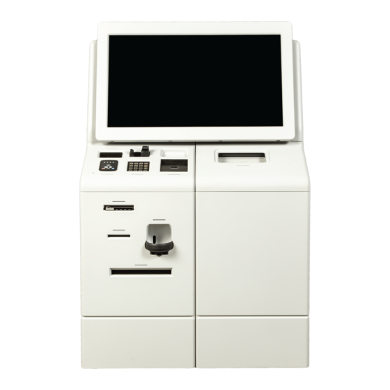
PRODUCT OVERVIEW CHAPTER 1 – PRODUCT OVERVIEW Kiosk Description Source Technologies’ 10-Series kiosk is a next-generation, self-service platform designed from the ground up to manage secure, distributed financial transactions and consumer banking. Kiosk Features and Options 10 Series Components Camera... - Page 13 PRODUCT OVERVIEW Rear View Rear View Power Cord Check Printer Connect Network Connect UPS (inside) 10-Series Kiosk Operator’s Manual | Source Technologies...
-
Page 14: Hardware Specifications
80MM WIDTH DIRECT THERMAL IMAGER 1D/2D BARCODE IMAGER COIN DISPENSE 1c, 5c, 10c, and 25c COIN DISPENSE POWER PROTECTION UPS BATTERY BACKUP Options ON DEMAND CHECK SECURE MICR CHECK PRINTER PRINTING BIOMETRICS PALM SCANNER 10-Series Kiosk Operator’s Manual | Source Technologies... -
Page 15: Chapter 2 - Getting Started
2.1 Opening the Safe and Changing the Default Combination The UL291 24 Hour Level 1 Cash Vault included in the 10 Series kiosk can use either a standard 6 Digit Combination Lock or an optional Audit Trail Combination Lock. See below to determine which of these lock systems is used in your kiosk and then go to the appropriate section for that lock’s operating instructions. -
Page 16: Operating Instructions: 6 Digit Combination Lock
• LED will flash red at ten (10) second intervals during the delay period. • At the end of the delay period, two (2) more consecutive invalid combinations will restart the five (5) minute delay period. • Keypad will not respond to keystrokes during delay period. 10-Series Kiosk Operator’s Manual | Source Technologies... - Page 17 Closing and Locking Safe Door A. Close safe door. B. Turn handle counterclockwise. Lock will automatically engage. Turn Handle in This Direction to Close C. Turn handle clockwise to verify that the lock is engaged. 10-Series Kiosk Operator’s Manual | Source Technologies...
- Page 18 COMMAND 3 - Delete User A. Enter Manager combination and hold down last digit of combination until Lock double signals and the LED stays on. B. PRESS 3. C. Enter User number (1-9). User is deleted. 10-Series Kiosk Operator’s Manual | Source Technologies...
-
Page 19: Operating Instructions: Audit Trail Combination Lock
• Entry of five (5) consecutive invalid combinations starts a three (3) minute delay period. Any failed entry attempt after the five invalid entries initiates a new three (3) minute delay period. 10-Series Kiosk Operator’s Manual | Source Technologies... - Page 20 The Auditcon 552 Audit Trail Lock has several options for the setting of Manager and User combinations. See Appendix A: Auditcon 2 Operating Instructions for details on how to set the lock combinations. 10-Series Kiosk Operator’s Manual | Source Technologies...
-
Page 21: Power On
Use small tool to press the UPS power button through the access hole 10-Series Kiosk Operator’s Manual | Source Technologies... -
Page 22: Loading Receipt Printer Paper
Use cabinet key to unlock the component cabinet. B. Pull component cabinet fully open and locate receipt printer on left side. Receipt printer is located on left side of cabinet underneath the check scanner 10-Series Kiosk Operator’s Manual | Source Technologies... - Page 23 C. Locate the check scanner lock plunger indicated by the arrow below and pull out to allow the check scanner to be moved. D. Slide the check scanner back to provide access to the receipt printer. 10-Series Kiosk Operator’s Manual | Source Technologies...
- Page 24 F. Place the paper roll and spindle into the printer paper holder as shown below. G. Route the paper into the printer paper guide and continue to push forward until the printer recognizes the paper and auto-loads. 10-Series Kiosk Operator’s Manual | Source Technologies...
- Page 25 H. Slide the check scanner back into position until you hear the lock plunger click into place. Verify that the check scanner is locked in place. I. Push the component cabinet back into position until it is latched in place. Receipt paper loading is complete. 10-Series Kiosk Operator’s Manual | Source Technologies...
-
Page 26: Loading Check Printer Paper
The paper loading procedure is the same for both trays. A. Unlock and open the component cabinet. Use cabinet key to unlock the component cabinet. B. Pull out the component cabinet and locate the check printer on the lower right-hand side. 10-Series Kiosk Operator’s Manual | Source Technologies... - Page 27 D. Open printer paper tray. E. Adjust the paper guides to match the size of the paper that you are loading. F. Flex, fan, and align the paper edges before loading. 10-Series Kiosk Operator’s Manual | Source Technologies...
- Page 28 I. Push printer shelf back into position until it closes against the magnetic latch. Push the component cabinet back into position until it is latched in place. K. Check printer paper loading is complete. 10-Series Kiosk Operator’s Manual | Source Technologies...
-
Page 29: Loading Coin Dispenser Canister
Use cabinet key to unlock the component cabinet. A. Unlock and open the component cabinet. B. From the left side of the cabinet, locate the coin dispenser power switch and power down the unit. Power Switch 10-Series Kiosk Operator’s Manual | Source Technologies... - Page 30 Unlock and remove the canister. Coin canister lock located on this side Turn CCW to unlock D. Using the handle located at the top, pull up and remove the coin canister. 10-Series Kiosk Operator’s Manual | Source Technologies...
- Page 31 F. Compress the two thumb points at the bottom of the canister cover (red arrows) and slide the cover upward. G. Continue sliding the cover upward and remove from the coin canister. 10-Series Kiosk Operator’s Manual | Source Technologies...
- Page 32 Re-install the coin canister into the coin dispenser and lock it in place. K. Power on the coin dispenser. L. Push the component cabinet back into position until it is latched in place. M. Coin loading is complete. 10-Series Kiosk Operator’s Manual | Source Technologies...
-
Page 33: Loading And Emptying The Cash Recycler
A. Unlock and fully open the component cabinet. Use cabinet key to unlock the component cabinet. B. See Section 2.1 – Opening Safe Door and open the door to the 24- Hr safe. 10-Series Kiosk Operator’s Manual | Source Technologies... - Page 34 D. Remove the cash cassettes by pulling straight up by the handle. NOTE: Remove only one cash cassette at a time and replace it in the same position from which it was removed. 10-Series Kiosk Operator’s Manual | Source Technologies...
- Page 35 Place notes here stage. If collecting notes, remove all notes, hold the stage with your hand and press the lever to release the stage. 10-Series Kiosk Operator’s Manual | Source Technologies...
- Page 36 K. After each cassette is loaded or emptied, push the lower unit back into the cash recycler until it is fully latched. L. Close and lock vault door. M. Cash Loading is Complete 10-Series Kiosk Operator’s Manual | Source Technologies...
-
Page 37: Powering Down The Kiosk
1. Navigate to Start > Power > Shut Down to shut down the OS. Integrated Computer Button OS Shut Down: 1. Unlock and open the component cabinet. Use cabinet key to unlock the component cabinet. 10-Series Kiosk Operator’s Manual | Source Technologies... - Page 38 Computer Module Located Here 3. Use a small tool to press and release the computer’s power button. This will shut down Windows and power off the computer. Computer Module Power Button Location 10-Series Kiosk Operator’s Manual | Source Technologies...
- Page 39 Power Down UPS Use small tool to press the UPS power button through the access hole Disconnect AC Power Cord Disconnect the kiosk’s power cord from the AC power outlet. Power Down Operation is Complete 10-Series Kiosk Operator’s Manual | Source Technologies...
-
Page 40: Chapter 3 - Component Operation
When the kiosk application calls for inserting or removing cash, the cash pocket shutter will open and the corresponding LED will flash. Insert (up to 200 notes max) or retrieve cash as needed where shown below. Cash Pocket Location 10-Series Kiosk Operator’s Manual | Source Technologies... -
Page 41: Emptying Reject Cassette
Use cabinet key to unlock the component cabinet. B. See Section 2.1 – Open Both Opening Safe Front and Top Door and open Safe Doors the front and top doors of the 24-Hr safe. 10-Series Kiosk Operator’s Manual | Source Technologies... - Page 42 D. Locate reject bin on the rear of the recycler. Reject Bin Lock Lever Located This Side Reject Bin E. Press the reject bin lock lever (63) down and remove the reject bin. 10-Series Kiosk Operator’s Manual | Source Technologies...
- Page 43 H. After the reject bin has been re-attached, push the lower unit back into the cash recycler until it is fully latched. I. Close and lock vault door. J. Close and latch the component cabinet. K. Emptying of Reject Bin is Complete 10-Series Kiosk Operator’s Manual | Source Technologies...
-
Page 44: Clearing Recycler Jams
Use cabinet key to unlock the component cabinet. See Section 2.1 – Opening Safe Door and open the front and top doors of the 24-Hr safe. Open Both Front and Top Safe Doors 10-Series Kiosk Operator’s Manual | Source Technologies... - Page 45 Pull latch (B-25) forward to unlock the recycler unit and pull out the unit LATCH B-25 until it is fully extended. NOTE: HANDLE Pull unit by latch or handle only. Clearing of Jams Figure 1a: Recycler Sections 10-Series Kiosk Operator’s Manual | Source Technologies...
- Page 46 COMPONENT OPERATION – Recycler Figure 1b: Recycler Sections UPPER UNIT SHUTTER UNIT BILL TRANSPORT VALIDATOR ESCROW Figure 1c: Opening the Upper Unit, Shutter Unit and Escrow 10-Series Kiosk Operator’s Manual | Source Technologies...
- Page 47 Cash Pocket Transport 1) Lift the Upper Unit (see Fig 1c). Turn Knob (B-18) and remove any jammed notes. 2) If the note can’t be removed, open the Cash Pocket Transport (B-4) for better access. 10-Series Kiosk Operator’s Manual | Source Technologies...
- Page 48 2) If the note is hard to remove, turn knob (B-6) to feed the note. 3) Press the lever (17) and close the Bill Validator until it is locked. 10-Series Kiosk Operator’s Manual | Source Technologies...
- Page 49 (B-14) to gain access. Escrow 1) Open the Escrow transport lid (B- 15) and removed any jammed notes. If the note is difficult to remove, turn the knob to move the note retainer. 10-Series Kiosk Operator’s Manual | Source Technologies...
- Page 50 1) Hold the lever (B-13) and lift the Escrow unit until it is locked. Lift the middle transport (B-24) and remove any jammed notes. If the note cannot be removed, turn knob (B-6) and feed the note until it is accessible. 10-Series Kiosk Operator’s Manual | Source Technologies...
- Page 51 4) Closing rear transport: (a) Hold the handle (64) firmly and lift the Rear Transport. (b) Lift the lock lever (62) to the arrowed direction. (c) Move the rear Transport downward slowly until it is locked. 10-Series Kiosk Operator’s Manual | Source Technologies...
- Page 52 Use handle to pull lower unit out. 2) Look for jammed notes at the entrance to the currency cassettes. 3) Remove each currency cassette and align any untidy notes. See Section 2.6 for details. 10-Series Kiosk Operator’s Manual | Source Technologies...
-
Page 53: Periodic Maintenance Requirement
4 months. Failure to perform periodic maintenance within the 4- month period can result in an increase in note jamming and other performance issues. NOTE: Cleaning and inspection of the cash recycler must be performed by properly trained and qualified service personnel. 10-Series Kiosk Operator’s Manual | Source Technologies... -
Page 54: Coin Dispenser
Loading Coins: See Section 2.5 for instructions on accessing and loading coins into the coin dispenser. Maintenance: No periodic maintenance is required for the coin dispenser. The outer surface of the dispenser may be cleaned with a soft damp cloth if necessary. 10-Series Kiosk Operator’s Manual | Source Technologies... -
Page 55: Check Scanner
D. The check scanner will process the check and, depending on the application, will either return the check or retain the check in internal storage. 10-Series Kiosk Operator’s Manual | Source Technologies... -
Page 56: Clearing Check Jams
CLEARING CHECK JAMS A. Unlock and open the component cabinet. Use cabinet key to unlock the component cabinet. B. Pull component cabinet fully open and locate Check Scanner Location the check scanner on left side. 10-Series Kiosk Operator’s Manual | Source Technologies... - Page 57 D. Slide the check scanner back to provide access for jam clearing. E. Loosen (2) thumb screws shown at right. 10-Series Kiosk Operator’s Manual | Source Technologies...
- Page 58 Verify that the check scanner is locked in place. I. Push the component cabinet back into position until it is latched in place. 10-Series Kiosk Operator’s Manual | Source Technologies...
-
Page 59: Stamp Installation And Replacement
90° from the back of the stamp slot. Insert the stamp and rotate clockwise to lock into the mechanism. Replacement stamps can be ordered from Source Technologies. See Chapter 5 for contact information. 10-Series Kiosk Operator’s Manual | Source Technologies... -
Page 60: Cleaning And Preventative Maintenance
OR TRY TO CLEAN THEM WITH ANY KIND OF CLEANER OTHER THAN WHAT IS RECOMMEDED. THIS MAY DAMAGE THE CONTACT IMAGE SENSORS. APPROVED CONTACT IMAGE CLEANER WIPES CAN BE OBTAINED FROM SOURCE TECHNOLOGIES. CONTACT IMAGE SENSOR Only use approved cleaning wipe Clean these areas with canned air 10-Series Kiosk Operator’s Manual |... -
Page 61: Hybrid Magnetic Stripe And Emv Card Reader
EMV Card Reader CLEANING EMV/MAG STRIPE CARD READER Use the approved Source Technologies Card Reader Cleaning Card to clean the EMV card reader as needed. Follow the card reader cleaning card written instructions for cleaning. EMV/Mag Stripe Reader cleaning cards can be ordered from Source Technologies. See Chapter 5 for contact information. -
Page 62: Omni-Directional Barcode Imager
For best results, place the barcode between 3 inches and 6 inches from the barcode imager window. The barcode should be facing the imager window. The LED indicator will light when the barcode imager is active. 10-Series Kiosk Operator’s Manual | Source Technologies... -
Page 63: Capturing A Driver's License Image
The imager window may be cleaned with a soft lint free cloth. The cloth may be moistened with water if necessary. The imager window is treated with an anti- reflective coating that may be damaged by harsh chemicals or cleaners. 10-Series Kiosk Operator’s Manual | Source Technologies... -
Page 64: Encrypted Pci-Compliant Pin Pad
PIN pad is active. CLEAR: Erases the last digit entered, CANCEL: Cancels the current transaction. CLEANING The PIN pad may be cleaned with a soft lint free cloth. 10-Series Kiosk Operator’s Manual | Source Technologies... -
Page 65: Receipt Printer
Receipts will be presented from the location shown below. The receipt printer LED indicator will blink to indicate the location of the receipt. Receipt Output LOADING RECEIPT PAPER See Section 2.3 for receipt paper loading instructions. 10-Series Kiosk Operator’s Manual | Source Technologies... -
Page 66: Clearing Jams
Use cabinet key to unlock the component cabinet. B. Pull component cabinet fully open and locate receipt printer on left side. Receipt printer is located on left side of cabinet underneath the check scanner 10-Series Kiosk Operator’s Manual | Source Technologies... - Page 67 C. Locate the check scanner lock plunger indicated by the arrow below and pull out to allow the check scanner to be moved. D. Slide the check scanner back to provide access to the receipt printer. 10-Series Kiosk Operator’s Manual | Source Technologies...
- Page 68 Located on This Side provide access to its printhead latch. F. Press the green printhead release latch in the direction indicated by the arrow. G. Rotate the printhead up into its service position. 10-Series Kiosk Operator’s Manual | Source Technologies...
-
Page 69: Cleaning
M. Push the component cabinet back into position until it is latched in place. CLEANING Use the Source Technologies Thermal Printer Cleaning Pen to clean the receipt printer printhead as necessary. A. Follow STEPS A – G above to access the receipt printer printhead. -
Page 70: Nfc Reader
NFC Reader A. When prompted by the application, hold your NFC device within 1.5 inches above the NFC reader. CLEANING The NFC Reader may be cleaned with a soft lint free cloth. 10-Series Kiosk Operator’s Manual | Source Technologies... -
Page 71: Palm Scanner
Palm Scanner SCANNING YOUR PALM A. When prompted by the application, center your palm over the scanner. (See Figure 3.9 for details on hand positioning during a palm scan) 10-Series Kiosk Operator’s Manual | Source Technologies... -
Page 72: Cleaning
Do not use water to clean the Sensor surface. It may cause a fault if water penetrates the Sensor unit. Do not use any organic solvents such as thinner, benzene, or anti-septic solution. Do not use any cleaning sprays. 10-Series Kiosk Operator’s Manual | Source Technologies... -
Page 73: Check Printer
Check Printer Output CLEARING PRINTER JAMS A. See Section 2.4, steps A – C for instructions on accessing the Check Printer. B. Potential Jam Locations: 10-Series Kiosk Operator’s Manual | Source Technologies... - Page 74 COMPONENT OPERATION – Check Printer C. Paper jam in Door A 1. Remove paper tray. 2. Open Door A 3. Remove Toner Cartridge 4. Remove Imaging Unit 10-Series Kiosk Operator’s Manual | Source Technologies...
- Page 75 6. Replace the Imaging Unit, Toner Cartridge, and Printer Tray; and close Door A. Push printer shelf back into position until it closes against the magnetic latch. Push the component cabinet back into position until it is latched in place. 10-Series Kiosk Operator’s Manual | Source Technologies...
- Page 76 2. Push printer shelf back into position until it closes against the magnetic latch. 3. Push the component cabinet back into position until it is latched in place. 10-Series Kiosk Operator’s Manual | Source Technologies...
- Page 77 3. Push printer shelf back into position until it closes against the magnetic latch. Push the component cabinet back into position until it is latched in place. G. Paper jam in Multi-Purpose Feeder The multi-purpose feeder is not used in this application. 10-Series Kiosk Operator’s Manual | Source Technologies...
-
Page 78: Cleaning
5. Re-connect the power cord and then turn on the printer. C. Push printer shelf back into position until it closes against the magnetic latch. D. Push the component cabinet back into position until it is latched in place. 10-Series Kiosk Operator’s Manual | Source Technologies... -
Page 79: Headphone Jack
COMPONENT OPERATION – Headphone 3.11 HEADPHONE JACK OPERATION If needed, plug your headphones (3.5mm connector) into the jack shown below. Headphone Jack 10-Series Kiosk Operator’s Manual | Source Technologies... -
Page 80: Chapter 4 - General Cleaning
OS and powering down the unit. ANTIMICROBIAL PLASTIC ENCLOSURE The plastic enclosure of the 10 Series kiosk is produced with an antimicrobial additive that is incorporated into the surface and substrate of material. The active ingredient is durable and will last for the lifetime of the product. -
Page 81: Touchscreen Display
Never Use these Cleaning Solutions on the Touchscreen Display • Acid • Abrasives • Steel Wool • Sponge with abrasives • Steel blades KIOSK COMPONENT CLEANING See the individual section for each component for cleaning instructions. 10-Series Kiosk Operator’s Manual | Source Technologies... -
Page 82: Chapter 5 - Contact Information
CONTACT INFORMATION CHAPTER 5 – CONTACT INFORMATION Source Technologies Attn.: Inside Sales 4205B Westinghouse Commons Drive, Charlotte, NC 28273 800.922.8501 (Voice) 704.522.8579 (Fax) www.sourcetech.com TECHNICAL SUPPORT CONTACT PROCEDURE Before contacting Technical Support, please gather the following information: 1. Kiosk serial number and REV. level 2. -
Page 83: Appendix A: Auditcon 2 Operating Instructions
To remove a lock from an operational mode, one can “shelve” the lock which places it in Shelved Mode. Most lock values are returned to the factory default. 10-Series Kiosk Operator’s Manual | Source Technologies... - Page 84 Personnel Classifications There are five different classifications of lock personnel: • Master User - The Master User performs the initial lock setup activities and can also shelve the lock. There is a maximum of one Master User per lock. The Master User combination will not open the lock.
- Page 85 The following chart shows the activities that can be performed by each type of user. Activity ✓ Set Master User PIN (p.6) ✓ Set Operating Mode (p. 7) ✓ Set Time Delay (p.7) ✓ Toggle Sound On/Off (p.8) ✓ Change Reporting Capabilities (p.9) ✓...
- Page 86 ETTING TARTED Lock Operating Conventions • The power source for the Auditcon 2 Lock Series is PowerStar Technology. With this technology an internal generator is used to create all necessary power. Important Note: The lock must be manually powered before each operation by briskly turning the dial back and forth •...
- Page 87 • After each keystroke a green flash is displayed. A beep will also sound if sound is toggled “on”. If the lock does not respond, either the lock has powered down or the key was not pressed properly. • After each accepted step of an operation, simultaneous green and red flashes display, prompting you to enter additional information for the next step of the operation.
- Page 88 Enter any valid two-digit User ID for the lock model (except “00”) followed by the pre-set PIN 502550 on the keypad. If the combination is entered successfully, the lock will respond as follows to indicate that the lock is ready to open: Dead Bolt - 1 slow green flash Slide Bolt - Continuous green flashes ...
- Page 89 Enter the two-digit Master ID 00 followed by the new Master User PIN again for verification. Record the new PIN and store it in a secure place. Note: Once the Master User PIN has been set, the factory combinations (User ID + PIN of “502550”) will no longer open the lock.
- Page 90 The default time delay is zero (i.e., the lock can be opened immediately after the combination requirements are met). Note: The time delay settings can be changed at any time. A change in delayed opening will not take effect until after the next opening. Caution: When Time Delay is set in a lock, designated Users (Access or Subordinate) become Time Delay Override Users.
- Page 91 Change Reporting Capabilities The default reporting mode of the lock enables all lock personnel (Master User, Access Users, Supervisors and Subordinate Users) to retrieve audit records or to retrieve User information. However, the Master User can limit the reporting capabili- ties, as shown in the following chart, depending on the lock model.
- Page 92 PERATIONS Operations found in this section are those that can be completed as needed in the course of normal lock operation after the lock has been set up. The following table denotes some of the storage differences and user limitations in lock models.
- Page 93 Press # and then 4. Enter the Master User combination or the Supervisor combination. Enter the Supervisor ID or User ID to be deleted. Enter the Supervisor ID or User ID to be deleted again for verification. If additional Supervisors or Users are to be deleted, repeat Steps 3-4 until all Supervisors/Users have been deleted.
- Page 94 To Unlock For a Dead Bolt, place dial in the HOME position. Enter a valid opening combination. If operating in Single User access and the combination is entered successfully, the lock indicates that it is ready to open by displaying the following: Dead Bolt - 1 slow green flash Slide Bolt - Continuous green flashes ...
- Page 95 For Dual User access, enter the second valid combination. If the combination is entered successfully, the lock indicates that it is ready to open by displaying the following: Dead Bolt - 1 slow green flash Slide Bolt - Continuous green flashes ...
- Page 96 Press # and then 2. Enter the Master User combination. Enter 08. Enter 08 again for verification. Note: A green flash followed by three red flashes indicates that the lock does not have enough power to perform the shelving operation. The lock will now open by entering any valid User ID for the lock model (except “00”) followed by 502550.
- Page 97 Enter the two-digit number that represents the hour again for verification. Enter the two-digit number that represents the minute(s) (00-59). Enter the two-digit number that represents the minute(s) again for verification. Note: It is recommended that you reset the time periodically in the Model 552 lock as there may be some drifting in the lock clock, up to 15 minutes per year.
- Page 98 Set Time Windows* * Battery Assist Recommended This feature enables the Master User to define time windows for access to the lock. A day/window code is required to identify the specific window being set. The following table describes the day/window codes to be used when setting Time Windows. Day/Window Code All Days...
- Page 99 Enter the two-digit number that represents the day/window code for the Time Window to be set. Enter the two-digit number that represents the day/window code again for verification. Enter the two-digit number that represents the starting hour (00-23) for the Time Window.
- Page 100 Add Holiday* * Battery Assist Required This feature enables the Master User to define up to 20 annual holidays in the lock. A two-digit holiday code (01-20) is used to identify a specific holiday. Each holiday entry is defined by a month, day, and a holiday exception time window. Caution: You should not add two different holiday codes for the same calendar date.
- Page 101 11. Enter the two-digit number that represents the starting minute (00-59) within the hour for the Holiday Exception Time Window. 12. Enter the two-digit number that represents the starting minute within the hour again for verification. 13. Enter the two-digit number that represents the ending hour (00-23) for the Holiday Exception Time Window.
- Page 102 OFTWARE ASED PERATIONS Upload Data to Lock As an alternative to defining setup data and user data manually at the lock, certain types of data can be defined at the PC using the Auditcon 2 Series Software and the information can then be uploaded (transferred) to the lock via a Smart Key. Program Lock If you choose the “Program the Lock”...
- Page 103 Add/Delete Users As an alternative to manually adding and deleting users at the lock, they can be added to and deleted from the system at the PC using the Auditcon 2 Series Software. The user data can then be transferred to the lock via a Smart Key. Note: The Add/Delete Users operation requires an SA key that has been properly prepared at the PC using the Auditcon 2 Series Software.
- Page 104 • lock mode changed • audit report retrieved • time delay override • beginning of timed lockout For a Model 552 lock, each transaction will include a date and time stamp. The number of audit records stored by the lock varies according to lock model. Refer to the Lock Models table at the top of page 9 for detailed information.
- Page 105 Notice: Information in this document is subject to change without notice. Kaba Mas shall not be liable for technical or editorial errors or omissions contained herein; nor for incidental or consequential damages resulting from the furnishing, performance or use of this material. ©...
Need help?
Do you have a question about the 10 Series and is the answer not in the manual?
Questions and answers