
Related Manuals for Sorel TDC 3


Summary of Contents for Sorel TDC 3
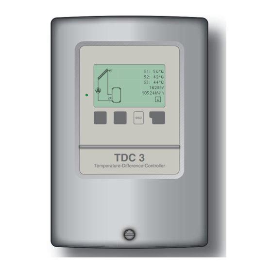
- Page 1 Temperature Difference Controller TDC 3 Installation and operating instructions TDC 3 Temperature-Difference-Controller Read carefully before installation, commissioning and operation...
-
Page 2: Table Of Contents
Content EC declaration of conformity Settings General instructions Tmin S1 Explanation of symbols Tmin S2 Changes to the unit Tmin S3 Warranty and liability Tmax S2 Tmax S3 ∆T R1 Specifi cations ∆T R2 About the controller Tset S3 Scope of supply Disposal and pollutants Hysteresis Hydraulic variants... -
Page 3: Ec Declaration Of Conformity
Safety instructions EC declaration of conformity By affi xing the CE mark to the unit the manufacturer declares that the Temperature- Difference-Controller 3, hereinafter refererred to as TDC 3 , conforms to the following relevant safety regulations: EC low voltage directive... -
Page 4: Changes To The Unit
Safety instructions Changes to the unit Changes to the unit can compromise the safety and function of the unit or the entire system. Danger Changes, additions to or conversion of the unit are not permitted without the writ- ten permission from the manufacturer It is likewise forbidden to install additional components that have not been tested together with the unit If it becomes clear that safe operation of the unit is no longer possible, for exam-... -
Page 5: Specifi Cations
Description of controller Specifi cations Electrical specifi cations: Mains voltage 230VAC +/- 10% Mains frequency 50...60Hz Power consumption Switched power Electronic relay R1 min.20W...max.120W for AC3 Mechanical relay R2 460VA for AC1 / 185W for AC3 Internal fuse 2A slow-blow 250V Protection category IP40 Protection class... -
Page 6: About The Controller
The controller menu contains headwords for the measured values and settings, as well as help texts or clearly-structured graphics. The TDC 3 can be used as a temperature difference controller for the various system variants illustrated and explained under B.5. -
Page 7: Hydraulic Variants
Description of controller Hydraulic variants The following illustrations should be viewed only as schematic dia- grams showing the respective hydraulic systems, and do not claim to be complete. The controller does not replace safety devices under any circumstances. Depending on the specifi c application, additional system Caution components and safety components may be mandatory, such as check valves, non-return valves, safety temperature limiters, scalding protec-... -
Page 8: Wall Installation
Installation Wall installation Install the controller only in dry areas and under the ambient conditions de- scribed under B.1 “Specifi cations”. Carry out the following steps 1-8. Caution 1. Unscrew cover screw completely C.1.1 2. Carefully pull upper part of housing from lower part. -
Page 9: Electrical Connection
Installation Electrical connection Before working on the unit, switch off the power supply and secure it against being switched on again! Check for the absence of power! Electrical connections may only be made by a specialist and in compli- Danger ance with the applicable regulations. -
Page 10: Installing The Temperature Sensors
Installation 1.Select necessary program/hydraulics C.2.1 (Fig. B5 resp. D.1 - D.20) 2.Open controller as described under C.1. 3.Strip cables by 55mmmax., insert, fi t the strain relief devices, strip the last 8-9mm of the wires (Fig. C.2.1) 4.Open the terminals using a suitable screwdriver (Fig. -
Page 11: D Terminal Connection Diagrams
Installation Terminal connection diagrams Solar with storage tank Low voltage max. 12VAC/DC connection Sensor side Mains side in the left-hand terminal compartment! max. 12V 230VAC Danger Caution Terminal: Connection for: S1 (2x) Sensor 1 collector S2 (2x) Sensor 2 storage tank S3 (2x) Sensor 3 (optional) The polarity of the sensors is freely se-... - Page 12 Installation Solar with bypass Low voltage max. 12VAC/DC connection Sensor side Mains side in the left-hand terminal compartment! max. 12V 230VAC Danger Caution Terminal: Connection for: S1 (2x) Sensor 1 collector S2 (2x) Sensor 2 storage tank S3 (2x) Sensor 3 forward fl ow The polarity of the sensors is freely se- lectable.
- Page 13 Installation Solar with 2 zone storage tanks Low voltage max. 12VAC/DC connection Sensor side Mains side in the left-hand terminal compartment! max. 12V 230VAC Danger Caution Terminal: Connection for: S1 (2x) Sensor 1 collector S2 (2x) Sensor 2 storage tank low S3 (2x) Sensor 3 storage tank top The polarity of the sensors is freely se-...
- Page 14 Installation Solar 2 coll. (east/west) Low voltage max. 12VAC/DC connection Sensor side Mains side in the left-hand terminal compartment! max. 12V 230VAC Danger Caution Terminal: Connection for: S1 (2x) Sensor 1 collector 1 S2 (2x) Sensor 2 storage tank S3 (2x) Sensor 3 collector 2 The polarity of the sensors is freely se- lectable.
- Page 15 Installation Solar 2 Storage tank/valve Low voltage max. 12VAC/DC connection Sensor side Mains side in the left-hand terminal compartment! max. 12V 230VAC Danger Caution Terminal: Connection for: S1 (2x) Sensor 1 collector S2 (2x) Sensor 2 storage tank 1 S3 (2x) Sensor 3 storage tank 2 The polarity of the sensors is freely se- lectable.
- Page 16 Installation D.11 Solar with follow-on storage tank/Solar & transfer“ Low voltage max. 12VAC/DC connection Sensor side Mains side in the left-hand terminal compartment! max. 12V 230VAC Danger Caution Terminal: Connection for: S1 (2x) Sensor 1 collector S2 (2x) Sensor 2 storage tank 1 S3 (2x) Sensor 3 storage tank 2 The polarity of the sensors is freely se-...
- Page 17 Installation D.13 Solar storage tank/pool Low voltage max. 12VAC/DC connection Sensor side Mains side in the left-hand terminal compartment! max. 12V 230VAC Danger Caution Terminal: Connection for: S1 (2x) Sensor 1 collector S2 (2x) Sensor 2 storage tank S3 (2x) Sensor 3 swimming pool The polarity of the sensors is freely se- lectable.
- Page 18 Installation D.15 Solar + cooling 2 Low voltage max. 12VAC/DC connection Sensor side Mains side in the left-hand terminal compartment! max. 12V 230VAC Danger Caution Terminal: Connection for: S1 (2x) Sensor 1 collector S2 (2x) Sensor 2 storage tank S3 (2x) Sensor 3 optional The polarity of the sensors is freely se- lectable.
- Page 19 Installation D.17 Solid fuel boiler Sensor side Low voltage max. 12VAC/DC connection Mains side max. 12V in the left-hand terminal compartment! 230VAC Danger Caution Terminal: Connection for: S1 (2x) Fühler 1 solid fuel boiler S2 (2x) Fühler 2 storage tank S3 (2x) Fühler 3 (optional) The polarity of the sensors is freely se-...
- Page 20 Installation D.19 Solar + valve + thermostat Low voltage max. 12VAC/DC connection Sensor side Mains side in the left-hand terminal compartment! max. 12V 230VAC Danger Caution Terminal: Connection for: S1 (2x) Sensor 1 collector S2 (2x) Sensor 2 storage tank low S3 (2x) Sensor 3 storage tank top The polarity of the sensors is freely se-...
- Page 21 Installation D.21 Universal 2x ∆T-controller Sensor side Mains side Low voltage max. 12VAC/DC connection max. 12V 230VAC in the left-hand terminal compartment! Danger Caution Terminal: Connection for: S1 (2x) Sensor 1 (control) S2 (2x) Sensor 2 (ref.+contr.) S3 (2x) Sensor 3 (reference) The polarity of the sensors is freely se- lectable.
-
Page 22: Display And Input
Operation Display and input The display (1), with its extensive text and graphics mode, is almost self-explanatory, allowing easy operation of the controller. The LED (2) lights up green when a relay is switched on. The LED (2) lights up red when operating mode “Off”... -
Page 23: Commissioning Help
Parametrisation Commissioning help The fi rst time the controller is turned on and after the language and time are set, a query appears as to whether you want to parametrise the controller using the commissioning help or not. The commis- sioning help can also be terminated or called up again at any time in the special functions menu. -
Page 24: Menu Sequence And Menu Structure
Operation Menu sequence and menu structure The graphics or overview mode appears when no key has been press for 2 min- utes, or when the main menu is exited by pressing “esc“. Pressing a key in graphics or overview mode takes you directly to the main menu. The following menu items are then avail- able for selection there: Current temperature values with explana-... -
Page 25: Measurement Values
Measurement values Measurement values The menu “1. Measurement values” serves to display the currently measured temperatures. The menu is closed by pressing “esc” or selecting “Exit measurement values”. Selecting “Info” leads to a brief help text explaining the measurement values. Selecting “Overview”... -
Page 26: Statistics
Statistics Statistics The menu “2. Statistics” is used for func- tion control and long-term monitoring of the system. The menu is closed by pressing “esc” or selecting “Exit statistics”. For analysis of the system data it is essential for the time to be set ac- curately on the controller. -
Page 27: Display Mode
Display mode Display mode Menu “3. Display mode” is used to defi ne the controller’s display for normal opera- tion. This display appears whenever two min- utes go by without any key being pressed. The main menu appears again when a key is pressed. -
Page 28: Operating Modes
Operating modes Operating modes In menu “4. Operating modes” the con- troller can either be placed in automatic mode, switched off, or placed in a manual operating mode. The menu is closed by pressing “esc” or selecting “Exit operating modes”. 4.1 Automatic Automatic mode is the normal operating mode of the controller. -
Page 29: Settings
Settings Settings The necessary basic settings required for the control function are made in menu “5. Settings”. This does not under any circumstances replace the safety facilities to be provided by the customer! Caution The menu is closed by pressing “esc” or select- ing “Exit settings”. -
Page 30: Tmax S2
Settings 5.4 Tmax S2 Switch-off temperature at sensor 2 If this value is exceeded at sensor 2 and the other conditions are also met, then the controller switches the associated pump and/or valve off. If sensor 2 falls below this value again and the other conditions are also met, then the controller switches the pump and/or valve on again. -
Page 31: Tset S3
Settings 5.7 ∆T R2 Switch-on/Switch-off temperature difference for relay R2 If this temperature difference between the reference sensors is exceeded and the other conditions are also met, then the controller switches the pump and/or the valve When the temperature drops to ΔT Off, then R2 is switched off. Settings range: ΔT from 4°C to 20°C / ΔTOff from 2°C to 19°C Settings range: ΔT 10°C / ΔT off 3°C. -
Page 32: Priority Sensor
Settings 5.10 Priority sensor Charging priority in systems with two storage tanks A setting must be made as to which storage tank (storage tank sensor) has priority for charging. Charging of the lower-priority storage tank is interrupted at regular intervals to check whether the temperature increase at the collector can enable charging of the higher-priority storage tank. -
Page 33: Party Function
Settings 5.15 „Party Function“ With the party function the storage temperature is heated up once to the reference temperature (TrefS3+hysteresis, respectively TecoS3+hysteresis in energy saving mode). The party mode is activated by pressing the „esc“-key for 3 seconds in the main menu. - Page 34 Settings...
-
Page 35: Protective Functions
Protective functions Protective functions Menu “6. Protective functions” can be used to activate and set various protective functions. This does not under any circumstances replace the safety facilities to be provided by the customer! Caution The menu is closed by pressing “esc” or select- ing “Exit settings”. -
Page 36: System Protection
Protective functions Protective functions 6.3 System protection priority protection System protection prevents overheating of system components by automatic shutdown of the solar pump. If “SProt Ton” is exceeded at the collector, the pump is switched off. The pump is activated again when the temperature drops below “SProt TOff”. Automatic shutdown - settings range: On / Off / Default: on SProt Ton - settings range: 60 °C to 150 °C / Default: 120 °C SProt Toff - settings range: 50 °C to Ton minus 5 °C / Default: 115 °C... -
Page 37: Cooling Functions
Protective functions 6.4.1 Cooling functions The hydraulic variants are set in menu „7.1 Program selection“ Hydraulic Variant D.14 Solar + cooling 1: If „CProt Ton“ is exceeded at S1, the cooler at R2 is switched on till the temperature drops to „CProt Toff“. If the storage tank exceeds „CProt Tmax storage“, the system is switched off. -
Page 38: Anti-Legionella
Protective functions 6.7 Anti-Legionella With the “AL function” activated the TDC 3 makes it possible to heat the storage tank to a higher temperature (“AL Tsetpoint S2”, provided that the energy source allows this. Time periods when the AL heat up is attempted are to be setup in the menu “AL times”... -
Page 39: Special Functions
Special functions Special functions Menu “7. Special functions” is used to set basic items and expanded functions. Other than the time all settings may only be made by a specialist. Caution The menu is closed by pressing “esc” or select- ing “Exit special functions”. -
Page 40: Commissioning
Special functions 7.4 Commissioning Starting the commissioning help guides you in the correct order through the basic set- tings necessary for commissioning, and provides brief descriptions of each parameter in the display. Pressing the “esc” key takes you back to the previous value so you can look at the se- lected setting again or adjust it if desired. -
Page 41: Start Aid Function
Special functions 7.7.1 Heat metering Activate or deactivate the heat metering function Settings range: On/off /default setting: Off 7.7.2 AF type Adjust the type of glycol that has been used in the system. Settings range: Ethylene/Propylene /default setting: Ethylene 7.7.3 Glycol portion Adjust the percentage of glycol that has been used in the system. -
Page 42: Speed Control
Special functions 7.9 Speed control If the speed control is activated, the TDC3 makes it possible to vary the speed of standard pumps at relay R1 by means of special internal electronics. This function should only be activated by a specialist. Depending on the pump and pump stage used, the minimum speed should not be set too low, because otherwise the pump or the system may be damaged. -
Page 43: Purging Time
Special functions 7.9.2 Purging time During this time the pump starts up at its full speed (100%) to ensure reliable starting. Only after this purging time does the pump run with speed control and switches to the max. or min. speed, depending on the variant set. Setting range: from 5 to 600 seconds/default setting: 8 seconds 7.9.3 Sweep time... -
Page 44: Menu Lock
Menu lock Menu lock Menu “8. Menu lock” can be used to secure the controller against unintentional changing of the set values. The menu is closed by pressing “esc” or select- ing “Exit menu lock”. The menus listed below remain completely accessible despite the menu lock being activated, and can be used to make adjustments if necessary: Measurement values Analysis... -
Page 45: Service Values
Service values Service values The menu “9. Service values” can be used for remote diagnosis by a specialist or the manu- facturer in the event of an error, etc. Enter the values at the time when the error occurs e.g. in the table. Caution The menu can be closed at any time by press- ing “esc”. -
Page 46: Malfunctions With Error Messages
Malfunctions Z.1. Malfunctions with error messages If the controller detects a malfunction, the red light fl ashes and the warning symbol also appears in the display. If the error (LED fl ashes + is no longer present, the warning symbol warning symbol) changes to an info symbol and the red light no longer fl... -
Page 47: Replacing The Fuse
Malfunctions Replacing the fuse Repairs and maintenance may only be performed by a specialist. Before working on the unit, switch off the power supply and secure it against Danger being switched on again! Check for the absence of power! Only use the supplied spare fuse or a fuse of the same design with the following specifi... - Page 48 Subject as a basic principle to errors and technical changes. Manufacturer: Your specialist dealer: SOREL GmbH Mikroelektronik Jahnstr. 36 D - 45549 Sprockhövel Tel. +49 (0)2339 6024 Fax +49 (0)2339 6025...
Need help?
Do you have a question about the TDC 3 and is the answer not in the manual?
Questions and answers
Why does night circulation come on? And how do I overcome this.