Table of Contents
Advertisement
Quick Links
Advertisement
Table of Contents

Related Manuals for Lithionics Battery GT Series


Summary of Contents for Lithionics Battery GT Series
- Page 1 GT Series Installation Manual Model Numbers GT12V450A-F24 GT12V600A-F24 GT24V300A-F24 GT48V150A-F24 GT51V150A-F24 GT12V600A-F27 GT24V300A-F27 GT48V150A-F27 GT51V150A-F27 *See Table 1 for model number details MiniBMS OptoLoop ® ® ® TECHNOLOGY TECHNOLOGY R10 – 10/23/2019...
-
Page 2: Important Safety Guidelines
Important Safety Guidelines This guide contains important safety instructions for the GT Series Battery System that must be followed during installation procedures. Completely read this manual and become familiar with all system components before attempting installation. Save this installation manual for future reference. - Page 3 Part III; of the UN Recommendations on the TRANSPORT OF DANGEROUS GOODS (Manual of Tests and Criteria, Fifth revised edition); [ST/SG/AC.10/11/Rev.5]. This Battery Module contains no mercury and Is RoHS Compliant. Please consult your local municipal authority for proper disposal. GT Series Installation Manual...
-
Page 4: System Specifications
(N2) Does not include 4/0 power cable’s weight as its length varies per application. (N3) Does not include 4/0 power cable, main power connector, or terminals. Please see www.lithionicsbattery.com for dimensions. (N4) "Bolted Fault Current" per NFPA-70E. GT Series Installation Manual... - Page 5 DD: Day of that Month YYYY: Year of Manufacture 001: Sequence of Battery Produced on That Day • Example: 01012018001 = manufactured on January 1, 2018 and it was the first battery produced on that day. GT Series Installation Manual...
-
Page 6: System Installation
2.7 Pressure Vent • It is recommended to install a ventilation hose onto the pressure vent barb when the Battery Module is in a location with poor ventilation. The hose shall direct the gases to the atmosphere. GT Series Installation Manual... - Page 7 Power/Reset switch, LED indicator, or serial datalogging. Be sure to connect the I/O connector if so equipped. 2.9 Initial Charge Cycle • Initially the system must be FULLY charged once to calibrate the BMS Unit to the Battery Module. Please read and follow the next section to perform this. GT Series Installation Manual...
-
Page 8: System Operation
Check that there is 0V at the output terminals with a voltmeter. 3.3 Charging • The charging device(s) connected to the GT Series Lithium Battery System must be programmed as per Table 1. • Charging may be performed at any time the system is powered On. - Page 9 Storing your battery at the correct specifications is important as it keeps the battery in the healthiest state possible for the fastest deployment when needed. • If the GT Series Lithium Battery System will not be in use for greater than 2 weeks, it is recommended to enable system storage. •...
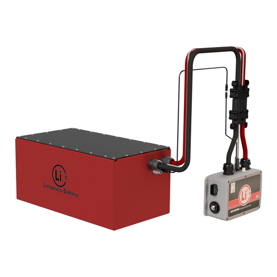
- Page 10 Figure 1: System Example Battery Module Pressure Vent Main Power Temperature Connectors Sensor Connectors NeverDie Disconnect Devices (See section 2.2 - Only applies to GT51V150A system) 300A Fast Acting Fuse GT Series Installation Manual...
Need help?
Do you have a question about the GT Series and is the answer not in the manual?
Questions and answers