Table of Contents

Related Manuals for fafnir VISY-Input 8


Summary of Contents for fafnir VISY-Input 8
- Page 1 VISY-Input 8 Digital 8-channel input module Version: Edition: 2016-09 Art. no.: 207166 FAFNIR GmbH • Schnackenburgallee 149 c • 22525 Hamburg • Germany • Tel.: +49 / 40 / 39 82 07–0 • Fax: +49 / 40 / 390 63 39...
-
Page 2: Table Of Contents
List of tables ................... 8 Appendix....................9 EU Declaration of Conformity ................9 Copyright: Reproduction and translation is only permitted with the written consent of the FAFNIR GmbH. The FAFNIR GmbH reserves the right to carry out product alterations without prior notice. -
Page 3: Overview
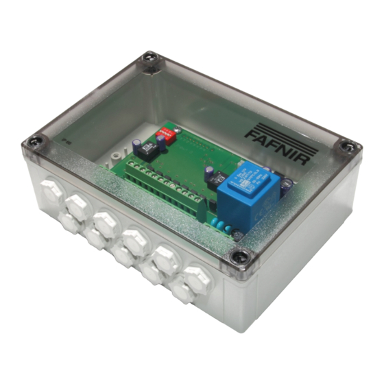
Overview VISY-Input 8 is a digital 8-channel input module, installed in a case with protection class IP66. It connects external alarm outputs to the VISY-X tank gauging system. With the VISY-Input 8, external alarm signals can be transmitted to the VISY-Command for central recording. -
Page 4: Requirements
Requirements To connect the VISY-Input 8 to the VISY-X system an interface card of version VI 4 or higher must be installed and connected to the communication adapter VISY-ICI 485. Installation The VISY-Input 8 is designed for wall mounting inside a building. -
Page 5: Connections
2.4.2 Connections 24-pin screw terminal for connecting the input signals 3-pin screw terminal for connecting the power supply 3-pin screw terminal for connecting the communication 2.4.3 Controls 2-pin plug connector to activate a terminating impedance for the RS-485 interface. Normally, the communication on the RS-485 network should be trouble-free with- out activation of the terminating impedance (jumper not plugged in), because the data rate is comparatively low. -
Page 6: Inputs
"In" and "+12 V" of the input. For the supply of external relay contacts VISY-Input 8 has an internal 12 V voltage supply. The inputs are galvanically connected by the internal 12 V voltage supply. The maximum cur- rent via the relay contact is limited to 10 mA ±10 %. -
Page 7: Configuration
For VISY-Input 8 the function of each input must be set by inserting or removing the corre- sponding jumper (see section 2.6). Further configuration of VISY-Input 8 is done - as usual for the VISY-X system - with the con- figuration software VISY-Setup. -
Page 8: Fault Diagnosis
Fault diagnosis VISY-Input 8 has several LEDs which help in diagnosing problems. The positions of the LEDs can be found in the figure 1. Transmit LED TxD (8) / Receive LED RxD (9) The two red communication LEDs indicate, whether data are received or transmitted from VISY-Input 8. -
Page 9: Led (12)
LED indicates a problem with the power supply or the AC adapter. Operating voltage LED (13) The green operating voltage LED indicates whether VISY-Input 8 is supplied with voltage. After switching on the power supply, the operating voltage LED illuminates continuously. If the LED flickers or is unlit, this indicates a problem with the power supply or the mains adapter. -
Page 10: Technical Data
10 mA ± 10% Table 2: Technical data List of figures Figure 1: VISY-Input 8 Design ..................2 Figure 2: Power supply screw terminal ................3 Figure 3: Input screw terminals ..................4 Figure 4: Communication screw terminal ................ 5 List of tables Table 1: Status LED ...................... - Page 12 FAFNIR GmbH Schnackenburgallee 149 c 22525 Hamburg Germany Tel.: +49 / 40 / 39 82 07–0 Fax: +49 / 40 / 390 63 39 E-mail: info@fafnir.de Web: www.fafnir.com...
Need help?
Do you have a question about the VISY-Input 8 and is the answer not in the manual?
Questions and answers