Table of Contents

Related Manuals for fafnir VISY-Output 8


Summary of Contents for fafnir VISY-Output 8
- Page 1 VISY-Output 8 8-Channel relay output module Version: Edition: 2016-09 Art. no.: 350072 FAFNIR GmbH • Schnackenburgallee 149 c • 22525 Hamburg • Germany • Tel.: +49 / 40 / 39 82 07–0 • Fax: +49 / 40 / 390 63 39...
- Page 2 © Copyright: Reproduction and translation is only permitted with the written consent of the FAFNIR GmbH. The FAFNIR GmbH reserves the right to carry out product alterations without prior notice. Table of contents...
-
Page 3: Table Of Contents
Table of contents Overview ....................1 Installation ....................1 2.1. Safety information ....................1 2.2. Requirements ..................... 2 2.3. Installation ......................2 2.4. Design and construction ..................2 2.4.1. Device information ..................... 2 2.4.2. Connections ....................... 2 2.4.3. Controls ......................3 2.4.4. -
Page 4: Overview
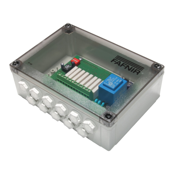
Overview VISY-Output 8 is an 8-channel relay output module, installed in a case with the protection IP66. It connects the VISY-X high-precision tank gauging system to external safety devices or alarm indicators. With VISY-Output 8, different alarm conditions detected by the VISY-X system will be transferred to external devices. -
Page 5: Requirements
2.2. Requirements To connect the VISY-Output 8 to the VISY-X system an interface card of version VI 4 or higher must be installed and connected to the communication adapter VISY-ICI 485. 2.3. Installation The VISY-Output 8 is designed for wall mounting inside a building. -
Page 6: Controls
2.4.3. Controls 2-pin plug connector to activate a terminating impedance for the RS-485 inter- face. Normally, the communication on the RS-485 network should be trouble- free without activation of the terminating impedance (jumper not plugged in), because the data rate is comparatively low. 4-way DIL switch, currently without function. -
Page 7: Connection Of The Relay Contacts
The communication line is to be connected to the terminals A, B and GND of the 3-pin screw terminal. For the wiring of VISY-Output 8 with VISY-ICI 485 it is recommended using a 3-core cable with signal ground (GND connection terminal) to increase the noise immunity. -
Page 8: Configuration
Configuration Further configuration of VISY-Output 8 is done - as usual for the VISY-X system - with the VISY-Setup configuration software. If a VISY-Output 8 will be connected to the VISY-X system, the data proto- col for communication with the VISY-Stick must always be set to “Multi Probe”... -
Page 9: Output Action After Hold Time
(passive), when the corresponding output is activated. The fail-safe mode provides the advantage that even in case of a failure in the power supply of the VISY-Output 8 an alarm can be signalled via de-energized (passive) relays. The following table shows the state of a relay depending on the configured relay mode and the state of the associated output. -
Page 10: Relay Delay
3.5. Maintenance Mode The maintenance mode is used to deactivate the outputs of the VISY-Output 8 temporari- ly. This function can for example be used during the configuration to prevent alarms via the relay contacts caused by incomplete configuration. The maintenance mode is turned on or off using the VISY-Setup configuration software, as far this function is supported by the used version. -
Page 11: Output Leds (9)
Status LED (10) The yellow status LED indicates the state of the communication between the VI interface card in the VISY-Command and the VISY-Output 8. The following table lists the possible states of the status LED and explains their meanings. -
Page 12: Relay Leds (11)
4.5. Operating voltage LED (12) The green operating voltage LED indicates whether VISY-Output 8 is supplied with volt- age. After switching on the power supply, the operating voltage LED illuminates continu- ously. If the LED flickers or is unlit, this indicates a problem with the power supply or the mains adapter. -
Page 13: Technical Data
2 A, P 50 VA Table 4: Technical data List of figures Figure 1: VISY-Output 8 Design ..................2 Figure 2: Power supply screw terminal ................3 Figure 3: Relay screw terminal ..................4 Figure 4: Communication screw terminal ................ 4 List of tables Table 1: Relay mode ....................... - Page 15 Blank page...
- Page 16 FAFNIR GmbH Schnackenburgallee 149 c 22525 Hamburg Germany Tel.: +49 / 40 / 39 82 07–0 Fax: +49 / 40 / 390 63 39 E-mail: info@fafnir.de Web: www.fafnir.com...
Need help?
Do you have a question about the VISY-Output 8 and is the answer not in the manual?
Questions and answers