Field Controls VentCool Summit S-Class Series Installation Manual
Hide thumbs
Also See for VentCool Summit S-Class Series:
- Installation, wifi setup and user manual (8 pages)
Table of Contents
Advertisement
Quick Links
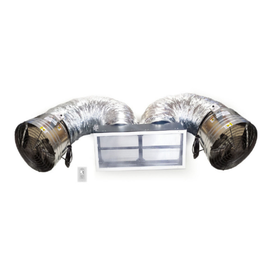
ITEMS INCLUDED:
•
(2) Fan Assembly with steel support straps, hardware and 20 foot power cord
•
(2) Duct Support Straps & hardware
•
(2) Acoustic Flex Duct, 7 foot length with collars
•
Gravity Damper Assembly
•
"Eggcrate" style Inlet Grille (white) with mounting screws
•
Wall Mount WTT Control (ON/OFF, 3 speed and 12-hour timer) and white Decora
wall plate
This device MUST be installed by a quali ed agency in accordance with the manufacturer's installation instructions. The de nition of
a quali ed agency is: any individual, rm, corporation or company which either in person or through a representative is engaged
in, and is responsible for, the installation and operation of HVAC appliances, who is experienced in such work, familiar with all the
precautions required, and has complied with all the requirements of the authority having jurisdiction.
Installed By:
INSTALLATION MANUAL
WHOLE HOUSE FAN SYSTEMS
MODELS: S6.5 (Generation 4)
Please retain these instructions after installation.
Phone:
www. eldcontrols.com
Installation Date:
P/N 780104700 03/20 Rev A
Advertisement
Table of Contents

Subscribe to Our Youtube Channel
Related Manuals for Field Controls VentCool Summit S-Class Series


Summary of Contents for Field Controls VentCool Summit S-Class Series
- Page 1 INSTALLATION MANUAL WHOLE HOUSE FAN SYSTEMS MODELS: S6.5 (Generation 4) ITEMS INCLUDED: • (2) Fan Assembly with steel support straps, hardware and 20 foot power cord • (2) Duct Support Straps & hardware • (2) Acoustic Flex Duct, 7 foot length with collars •...
- Page 2 (THIS PAGE LEFT INTENTIONALLY BLANK) P/N 780104700 03/20 Rev A page 2 of 20...
-
Page 3: Safety Considerations
DO NOT INSTALL DAMAGED EQUIPMENT. If you suspect this fan has been damaged during shipping, contact Field Controls technical support by phone at 1.800.742.8368, or email at eldtec@ eldcontrols.com. Whole House Fans are designed to be installed within a home’s attic, which makes them and their sub-components di cult to access once installed. -
Page 4: Electrical Requirements
GRAVITY DAMPER INFORMATION The VentCool Summit Series fan systems include gravity-closed gravity damper doors that are opened by air pressure created by fan operation. The dampers serve to block entry of air from the attic into the living space, and are provided with foam sealing and insulating material in the doors to reduce heat transfer from the attic space. -
Page 5: Ventilation Requirements
VENTILATION REQUIREMENTS It is very important that the attic be su ciently ventilated for the fan system to operate properly. Without adequate ventilation, hot air exhausted from the home cannot easily escape from the attic, which creates back- pressure that will substantially reduce the fan’s performance. Operating this fan in an attic with less net free ventilation area than recommended will decrease its air ow and energy e ciency. - Page 6 WHERE TO LOCATE THIS FAN The best location for this fan is determined by an under- standing of its theory of operation: As a home heats up during the day, a large amount of heat is retained in its structure and contents. These materials give up their heat slowly and, in doing so, continue to heat the home’s inte- rior even though the outdoor temperature may, in fact, be very comfortable in the evening and at night.
- Page 7 INSTALLATION: GRAVITY DAMPER GRAVITY DAMPER ORIENTATION NOTE The ideal orientation of unit’s gravity damper is in a level position. If necessary, however, the damper can be installed at a slight angle. Before beginning the installation, make sure that the fan assembly is undamaged, and that the fan blade rotates freely.
- Page 8 4. Make sure that the exact location chosen for the rough opening will allow installation of the eggcrate inlet grille, and will not interfere with any lighting xtures, smoke alarms, or other objects installed in the ceiling. 5. Remove any insulation from the area of the exact chosen location, and make sure that no wiring, plumbing, bracing or other building elements will interfere with the damper as-...
- Page 9 INSTALLATION: FAN & DUCT NOTES: • The fan assembly must be soundly supported by attachment to structurally sound framing. Provide additional framing with minimum 2-by-4 lumber as needed for fan support. • The fan assembly should be positioned with at least 24” of free space in front of the fan, for air to be freely blown into the attic by the fan.
- Page 10 6. Using the black woven poly strapping, support the acoustic ex duct by attaching the strapping to attic fram ng as shown. Fold each end over a large washer 2-3 times and fasten to the framing by driving the supplied 1” drywall screws or other appropriate fasteners through the washer and into the framing. desired.
- Page 11 4. Connect the cable to the wall control (WTT). Plug the cable into the “RED” RJ12 Connector on the back side of WTT. Refer to FIGURE 7 and DIAGRAM 1 for cable connections. 5. Attach the wall control (WTT) and cover plate to the plastic retro t box (refer to FIGURE 8). FIGURE 8 - ATTACH WALL FIGURE 7 - PLUG CABLE TO WALL CONTROL CONTROL AND COVER PLATE...
- Page 12 DIAGRAM 1: VC SUMMIT S6.5 (GEN4) CONNECTION DIAGRAM DIAGRAM 2: VC SUMMIT S2-S6.5 (GEN4) FAN WIRING page 12 of 20 P/N 780104700 03/20 Rev A...
-
Page 13: Operation
FIGURE 10 : STANDARD WALL CONTROL SYSTEM (SPEED TEMPERATURE OR TIME) OPERATION Before starting this fan for the rst time, verify that: • All wiring and connection have been made according to this manual and all applicable wiring codes and standards. - Page 14 Switching wall control between Temperature and Timer Control Modes: 1. Switch wall control to Temperature Control from Timer Control mode: a. Press MODE button on WTT then press DOWN ARROW button to select TEMPERATURE CONTROL. 2. Switch wall control to Timer Control from Temperature Control mode: Press MODE button on WTT then press UP ARROW button to select TIMER CONTROL.
-
Page 15: Important Operating Tips
Adjusting the Timer Setting: Press and hold the ARROW UP or ARROW DOWN buttons individually to adjust current Timer Interval set- ting. Note: If fan is operating, the new Timer Interval setting adjustment is temporary. Once time period times out, Timer Interval will revert back to original Timer Interval setting. But if fan is OFF and you adjust the Timer Interval , the new Timer Interval is saved as the permanent setting. -
Page 16: Maintenance And Troubleshooting
Step 6 Set the Number of Fan Speeds in the INSTALLATION: WIRING AND CONTROL section to change number of fan speeds of the wall control (WTT) device. If the suggestions above do not work, contact Field Controls technical support at 800.742.8368 or by email eldtec@ eldcontrols.com for further assistance. Technical manuals are available on our website at www. - Page 17 IN 4P CONNECTOR FOR CCW ROTATION Optional Upgrade Components for Controlling your Ventcool Summit Series Whole House Fan (Generation 4): Contact Field Controls Sales team for purchasing any of the following optional Upgrade components. These new products will be available in 2021.
-
Page 18: Specifications
SPECIFICATIONS* Speed Settings: Gravity Damper Rough Opening Dimensions: S6.5– 14.3 inches x 36.3 inches Grille Construction: Aluminum Cube Core, Steel frame (White Powder Coated) Fan Diameter: S6.5 – 18.75 Inches Diameter Duct Length: 7 feet Duct Diameter: S6.5 – 16 Inches Electrical: 115VAC, 15 AMP DEDICATED POWER Fan Motors: (HP/RLA, each motor) - Page 19 P/N 780104700 03/20 Rev A page 19 of 20...
- Page 20 This manual may be downloaded and printed from the Field Controls website (www. eldcontrols.com) WARRANTY For warranty information about this or any Field Controls product, visit: www. eldcontrols.com/ventCool Field Controls Technical Support 1.800.742.8368 eldtec@ eldcontrols.com Phone: 252.522.3031 • Fax: 252.522.0214 www.fieldcontrols.com...
Need help?
Do you have a question about the VentCool Summit S-Class Series and is the answer not in the manual?
Questions and answers