Table of Contents
Advertisement
Quick Links
Instructions - Parts
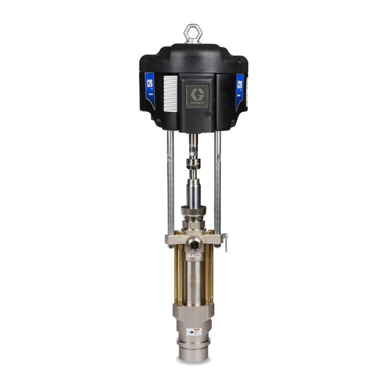
Xtreme
Carbon Steel Pumps with Hard Chrome Rod for Sealer Applications.
Part No. 24N976
Important Safety Instructions
Read all warnings and instructions in this
manual. Save these instructions.
See page 2 for model information, including maximum working pressure.
®
Pumps
3A2851A
EN
Advertisement
Table of Contents

Related Manuals for Graco Xtreme 24N976


Summary of Contents for Graco Xtreme 24N976
- Page 1 Instructions - Parts ® Xtreme Pumps 3A2851A Carbon Steel Pumps with Hard Chrome Rod for Sealer Applications. Part No. 24N976 Important Safety Instructions Read all warnings and instructions in this manual. Save these instructions. See page 2 for model information, including maximum working pressure.
-
Page 2: Table Of Contents
Graco Standard Warranty ....20 Graco Information ......20 Related Manuals Manuals are available at www.graco.com. -
Page 3: Warnings
Warnings Warnings The following warnings are for the setup, use, grounding, maintenance, and repair of this equipment. The exclama- tion point symbol alerts you to a general warning and the hazard symbols refer to procedure-specific risks. When these symbols appear in the body of this manual or on warning labels, refer back to these Warnings. Product-specific hazard symbols and warnings not covered in this section may appear throughout the body of this manual where applicable. - Page 4 Warnings WARNING EQUIPMENT MISUSE HAZARD Misuse can cause death or serious injury. • Do not operate the unit when fatigued or under the influence of drugs or alcohol. • Do not exceed the maximum working pressure or temperature rating of the lowest rated system com- ponent.
-
Page 5: Important Isocyanate (Iso) Information
Important Isocyanate (ISO) Information Important Isocyanate (ISO) Information Isocyanates (ISO) are catalysts used in two component materials. Isocyanate Conditions Moisture Sensitivity of Isocyanates Exposure to moisture (such as humidity) will cause ISO to partially cure; forming small, hard, abrasive crystals, Spraying or dispensing materials containing which become suspended in the fluid. -
Page 6: Changing Materials
Important Isocyanate (ISO) Information Changing Materials NOTICE Changing the material types used in your equipment requires special attention to avoid equipment damage and downtime. • When changing materials, flush the equipment mul- tiple times to ensure it is thoroughly clean. •... -
Page 7: Installation
Installation Installation Grounding Fluid supply container: follow local code. Object being sprayed: follow local code. Solvent pails used when flushing: follow local code. Use only conductive metal pails, placed on a grounded surface. Do not place the pail on a nonconductive sur- The equipment must be grounded. -
Page 8: Air Line Accessories
Installation Air Line Accessories Fluid Line Accessories Install the following accessories in the order shown in . 1, using adapters as necessary. For air-powered pumps, install the following accessories in the order shown in F . 1, using adapters as neces- sary. - Page 9 Installation TI8433a . 1: Typical Installation, Air-Powered Pumps Key: Pump Electrically Conductive Fluid Supply Hose Wall Bracket Fluid Whip Hose Air Line Lubricator Gun Swivel Bleed-type Master Air Valve (required) Airless Spray Gun Pump Air Regulator Fluid Suction Kit Electrically Conductive Air Supply Hose Main Air Supply Line Air Line Filter Air Line Drain Valve...
-
Page 10: Operation
Operation Operation Pressure Relief Procedure Startup Follow the Pressure Relief Procedure when- 1. Connect the suction kit (T) to the pump's fluid inlet, ever you see this symbol. and place the tube into the fluid supply. 2. Close the air regulator (F) then open the pump's bleed-type master air valve (E) to prepare the pump’s power source. -
Page 11: Shutdown
Operation Shutdown Relieve the pressure, page 10. Stop the pump at the bottom of its stroke to prevent fluid from drying on the exposed displacement rod and damaging the throat packings. . 2. Bleeder Valve and Wet-Cup 3A2851A... -
Page 12: Maintenance
See F . 2. Check the packing nut (AC) daily. Keep the 6. Remove gun from hose. See gun manual to further ™ wet-cup filled with Graco Throat Seal Liquid (TSL ) or clean gun. compatible solvent. 7. Follow Pressure Relief Procedure, page 10, and Adjust the packing nut weekly so it is just snug;... -
Page 13: Troubleshooting
Troubleshooting Troubleshooting 1. Follow Pressure Relief Procedure, page 10. 2. Check all possible causes and problems before dis- assembling pump. Problem Cause Solution Does not operate. Valve closed or clogged. Clear air line; increase air supply. Check that valves are open. Fluid hose or gun obstructed. -
Page 14: Repair
Repair Repair Required Tools 5. Remove clip (108), and slide coupling cover (104) up to remove coupling (103). • Rubber mallet • Set of adjustable wrenches • Torque wrench • Thread lubricant • Anti-seize lubricant ® ™ • Loctite 2760 or equivalent Replace the Lower TI8264a... -
Page 15: Parts
Parts Parts Xtreme Pumps with NXT Air Motors Part Description Qty. N65RH0 MOTOR, see 311238 24N942 LOWER 244819 COUPLING ASSY 197340 COVER, coupling 15H392 ADAPTER 257150 ROD, tie 101712 244820 CLIP, hairpin; with lanyard 3A2851A... -
Page 16: Dimensions
Dimensions Dimensions Wall Mount Packages and Pump Packages Front View Side View TI8424a TI8425a Wall Mount Dimensions NOTE: Dimensions based on largest air motor and lower combination. 14.0 in. 17.75 in. 29.0 in. 19.25 in. 43.0 in. 18.9 in. 16.2 in. (355.6 mm) (450.6 mm) (736.6 mm) -
Page 17: Mounting Hole Layouts
Mounting Hole Layouts Mounting Hole Layouts NXT Model 6500 Four 3/8-16 Mounting Holes 6.186 in. (157 mm) Three 5/8-11 Tie Rod Holes 6.186 in. (157 mm) TI8069A 3A2851A... -
Page 18: Technical Data
Technical Data Technical Data Ratio......... See Models, page 2. Maximum fluid working pressure . - Page 19 Technical Data Pump Performance Charts Fluid Outlet Pressure Pump Air Consumption To find fluid outlet pressure (MPa/bar/psi) at a specific To find air consumption at a specific flow (lpm/gpm) and flow (lpm/gpm) and operating pressure (A/B/C): operating pressure (A/B/C): 1. Locate desired flow at bottom of chart. 1.
-
Page 20: Graco Standard Warranty
With the exception of any special, extended, or limited warranty published by Graco, Graco will, for a period of twelve months from the date of sale, repair or replace any part of the equipment determined by Graco to be defective.
Need help?
Do you have a question about the Xtreme 24N976 and is the answer not in the manual?
Questions and answers