Table of Contents
Advertisement
Quick Links
Planning and installation
Basic Line Ai1 Geo
Heating station
WATERKOTTE GmbH, Gewerkenstraße 15, D-44628 Herne
Tel.: +49 2323 9376 0, Fax: +49 2323 9376 99
Service: +49 2323 9376 350
E-Mail: info@waterkotte.de Internet: http://www.waterkotte.de
1 / 60
12.11.2015
Z21826
Copyright 2013 by: WATERKOTTE GmbH. Subject to changes
Advertisement
Table of Contents

Related Manuals for WATERKOTTE Basic Line Ai1 Geo


Summary of Contents for WATERKOTTE Basic Line Ai1 Geo
- Page 1 Heating station WATERKOTTE GmbH, Gewerkenstraße 15, D-44628 Herne Tel.: +49 2323 9376 0, Fax: +49 2323 9376 99 Service: +49 2323 9376 350 E-Mail: info@waterkotte.de Internet: http://www.waterkotte.de 1 / 60 12.11.2015 Z21826 Copyright 2013 by: WATERKOTTE GmbH. Subject to changes...
- Page 2 This publication has been prepared with all reasonable care. WATERKOTTE GmbH does not assume any liability for remaining errors or omissions, or for possible damages. 2 / 60 12.11.2015...
-
Page 3: Table Of Contents
Operator's duty of care ...................... 9 Other applicable documents ....................9 Functional principle of an heat pump ..................10 Description of operation Basic Line Ai1 Geo ..............10 Product description ....................... 11 Overview .......................... 11 Components and installation ....................13 Heating system Basic Line Ai1 Geo ................. - Page 4 Electrical wiring diagram (1x 230 V) ..............39 Controller ......................... 40 Terminals ......................... 41 Plan and MSR-equipment...................... 42 Hydraulic diagramm Basic Line Ai1 Geo ................. 43 Commissioning ........................44 12.1 Pre-startup checks ......................44 12.2 Initial start-up of the machine ................... 45 12.3 Control of the entire operation ..................
- Page 5 Connection diagram ......................50 16.1 Basic Line Ai1 Geo with underfloor heating ..............50 16.2 Basic Line Ai1 Geo with underfloor heating and individual room control ......51 16.3 Basic Line Ai1 Geo with hydraulical deflector ..............52 16.4 Basic Line Ai1 Geo with radiators ..................53 16.5 Legend hydraulic schemes ....................
-
Page 6: Safety
Safety 1 Safety 1.1 Intended use Your WATERKOTTE heat pump is used for space heating and cooling, and heat- ing of domestic water. Project planning of the heat source system must be performed in compliance with the technical information provided by WATERKOTTE for layout of heat source sys- tems. -
Page 7: Environmental Protection
Original spare parts are specially designed for your heat pump. Externally pro- cured parts provide no guarantee that they are designed and manufactured in compliance with relevant usage and safety requirements. Parts and special equipment not delivered by WATERKOTTE are not approved for use on the heat pump. 1.4 Hazards... - Page 8 Risk of total loss! The device may only be switched on when the hydraulic circuits are completely filled and vented, and all electrical connections are properly. 8 / 60 12.11.2015 Z21826 Copyright 2013 by: WATERKOTTE GmbH. Subject to changes...
-
Page 9: Specific Types Of Hazards
1.6 Operator's duty of care Your WATERKOTTE heat pump has been designed and built on the basis of a risk analysis and after careful selection of standards to be observed. Thus, your heat pump is state-of-the-art and provides for maximum safety. In practice, however, this safety can only be ensured by taking all necessary measures. -
Page 10: Functional Principle Of An Heat Pump
Figure 1: Energy share while using a geothermal energy pump 2.1 Description of operation Basic Line Ai1 Geo The WATERKOTTE heating central Basic Line Ai1 Geo uses a heat pump as heat generator. At the heat source side the medium is cooled down in the vaporizer about 3 to 4K with the help of this device. -
Page 11: Product Description
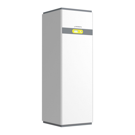
Product description 3 Product description 3.1 Overview Figure 2: Basic Line Ai1 Geo (closed) Display ON/ OFF-switch 11 / 60 12.11.2015 Z21826 Copyright 2013 by: WATERKOTTE GmbH. Subject to changes... - Page 12 Product description Figure 3: Basic Line Ai1 Geo (open) Tank for domestic hot water Control board Connecting terminal (400 V – series) 12 / 60 12.11.2015 Z21826 Copyright 2013 by: WATERKOTTE GmbH. Subject to changes...
-
Page 13: Components And Installation
Manufacturing quality is carried out based on ISO 9001ff, supplemented by an au- tomated computer-monitored quality test (pressure stress and helium leak test) in addition to inspection of all parameters in a subsequent trial run. 13 / 60 12.11.2015 Z21826 Copyright 2013 by: WATERKOTTE GmbH. Subject to changes... -
Page 14: Electrical Equipment
The heat pump control (control panel is pictured) is included in the delivery scope of the WATERKOTTE heat pump. Use in other than WATERKOTTE heat pumps will void any warranty claim. The control is used to control and monitor heating systems that are operated with WATERKOTTE compact heat pumps according to technical guidelines of WATERKOTTE head pump GmbH. -
Page 15: Cop-Counter
Components and installation 4.3.6 COP-counter A WATERKOTTE COP counter is already integrated in the heat pump control. For Operating manual for Heat pump control. additional information, please refer to 4.3.7 Options Mixer accessories: sensor, three ways valve, additional control module. -
Page 16: Transport
Ensure proper disposal of packaging materials. Packaging materials, such as nails or other metal or wooden parts, may cause injuries. Please also read chapter "General safety information“. 16 / 60 12.11.2015 Z21826 Copyright 2013 by: WATERKOTTE GmbH. Subject to changes... - Page 17 After carton is removed or opened it is not permitted to tilt the unit by applying pressure to the pipelines or housing enclosure; this could result in bent housing parts and pipelines. 17 / 60 12.11.2015 Z21826 Copyright 2013 by: WATERKOTTE GmbH. Subject to changes...
-
Page 18: Installation
An additional improvement can be obtained by creating an heat pump size corresponding base (see below), are achieved with an insulat- ing pad made of polyurethane rubber. 18 / 60 12.11.2015 Z21826 Copyright 2013 by: WATERKOTTE GmbH. Subject to changes... -
Page 19: Heat Pump Base
Insulation strip (polyethylen / PE) Insulation material (3 layer, polyurethan rubber) Supporting subsurface Insulation material Screed Concrete plinth Dimensions concrete plinth (mm) Series Width Depth High Basic Line Ai1 19 / 60 12.11.2015 Z21826 Copyright 2013 by: WATERKOTTE GmbH. Subject to changes... -
Page 20: Installation Of Heat Pump And Tank
Z15312 Installation document: Acceptance and Installation Data Isolated removing Tool (for the removing of the housing) Z20086 Z13122 Outdoor wall mounted sensor (accessories box heat pump) 20 / 60 12.11.2015 Z21826 Copyright 2013 by: WATERKOTTE GmbH. Subject to changes... -
Page 21: Installation
Align the heat pump module in a horizontal position. To do this, use the set screws for height adjustment (under the corners of the unit), width across flats 30 m. 21 / 60 12.11.2015 Z21826 Copyright 2013 by: WATERKOTTE GmbH. Subject to changes... -
Page 22: Dismantlement/ Assembly Of The Heat Pump (Service Event)
Lift the storage module and put it on a plane area Figure 7: Rear safed with lens-head screws (Pos. 1) Note: For lifting the storage module you need sveral people. The module weights about 59 kg. 22 / 60 12.11.2015 Z21826 Copyright 2013 by: WATERKOTTE GmbH. Subject to changes... -
Page 23: Temperature Sensor
Pos.1 –Raise the switch out of the suspension clamp with the screwdriver. Pos.2 –The plug of the bus cable has a retaining tab. Press this up and unplug the cable. 23 / 60 12.11.2015 Z21826 Copyright 2013 by: WATERKOTTE GmbH. Subject to changes... -
Page 24: Installation Und Connection
G 1¼“ a (heat pump exit) flat sealing, seal: Z14872 Heating flow G 1¼“ a flat sealing: Z14872 Heating return G 1¼“ a flat sealingl: Z14872 24 / 60 12.11.2015 Z21826 Copyright 2013 by: WATERKOTTE GmbH. Subject to changes... -
Page 25: Connecting Dimensions
Installation und connection 8.2 Connecting dimensions Figure 8: All connections in mm, Basic Line Ai1 Geo (rear) 25 / 60 12.11.2015 Z21826 Copyright 2013 by: WATERKOTTE GmbH. Subject to changes... -
Page 26: Connection To Heating System
Mounting position see diagram (chap.16). A second pressure expansion tank must be connected if, for instance, a compact condensing boiler (for domestic hot water production with the WATERKOTTE wa- ter heater) or a buffer tank (for heating) is planned. 8.3.2 Heat pump with underfloor heating ... -
Page 27: Heat Pump With Radiators (Natural Cooling Not Possible)
(geothermal probes). The groundwater, by connection to a well system, using an accessories kit available from WATERKOTTE to monitor the flow at heat source side and separation heat exchanger (heat source side). ... - Page 28 Use stainless steel, copper, brass or plastic - such as PE - for instance. Steel pipes and other steel components should also be avoided in groundwa- ter systems. 28 / 60 12.11.2015 Z21826 Copyright 2013 by: WATERKOTTE GmbH. Subject to changes...
-
Page 29: Residual Head
5006.5 5008.5 5010.5 Flow rate m³/h T 4K 20/7.5 20/7.5 20/7.5 Pump (class A) 20/7.5 Residual headT 4K ** medium circle 15% Ethylen-Glykol and 85% water 29 / 60 12.11.2015 Z21826 Copyright 2013 by: WATERKOTTE GmbH. Subject to changes... -
Page 30: Water Glycol Systems
8.4.2 Water glycol systems Since Basic Line Ai1 Geo is already equipped with a heat source pump, the heat source system can be directly connected to the heat pump. There is no need for an additional heat source module. To prevent frost damage, the heat source sys- tem must be filled with about 30 % WATERKOTTE ethylene glycol (freezing point at about -15 °C). -
Page 31: Water-Glycol Mixture In The Installation
Water-Glycol mixture in the installation Ground water plants without cooling: Minimum 15 % WATERKOTTE ethylene- glycol in the separating heat exchanger – vaporizer circle. Earth plants without cooling: Minimum 25 % WATERKOTTE ethylene-glycol in the heat source circle. 31 / 60 12.11.2015... -
Page 32: Flow Monitoring
Cleaning can be performed by flushing. The plate heat exchanger is to be flushed with a suitable cleaning agent in counter-flow direction. 32 / 60 12.11.2015 Z21826 Copyright 2013 by: WATERKOTTE GmbH. Subject to changes... - Page 33 If chemicals are used for cleaning, please ensure that they are compatible with stainless steel or copper. Failure to comply can result in destruction of plate heat exchanger! 33 / 60 12.11.2015 Z21826 Copyright 2013 by: WATERKOTTE GmbH. Subject to changes...
-
Page 34: Electrical Work
The relay circuit board (WWPR) may only be connected or removed by pro- fessionals. Install and remove relay circuit board only in voltage-free state. All connections performed directly at the plug connections of the relay circuit 34 / 60 12.11.2015 Z21826 Copyright 2013 by: WATERKOTTE GmbH. Subject to changes... -
Page 35: Electrical Heat Generator For Startup And Standby
The heat source cannot regenerate itself continuously; in unfavourable cases the ground can be subject to frost action in areas with horizontal withdrawal. 35 / 60 12.11.2015 Z21826 Copyright 2013 by: WATERKOTTE GmbH. Subject to changes... -
Page 36: Startup Of Electrical Heat Generator (Ewe)
When performing temporary installation, sensor might have to be mounted on board, which is fastened to a wall (outdoor). 36 / 60 12.11.2015 Z21826 Copyright 2013 by: WATERKOTTE GmbH. Subject to changes... -
Page 37: Instalation Of The Cabling
(Pos.2). Figure 10: Installation position of terminal (Pos..2) For the connection of external cabling, it is necessary to work at the electrical switch panel. 37 / 60 12.11.2015 Z21826 Copyright 2013 by: WATERKOTTE GmbH. Subject to changes... -
Page 38: Electrical Connection
Electrical work 9.5 Electrical connection 9.5.1 Electrical wiring diagram (3x 400 V) 38 / 60 12.11.2015 Z21826 Copyright 2013 by: WATERKOTTE GmbH. Subject to changes... -
Page 39: Electrical Wiring Diagram (1X 230 V)
Electrical work 9.5.2 Electrical wiring diagram (1x 230 V) 39 / 60 12.11.2015 Z21826 Copyright 2013 by: WATERKOTTE GmbH. Subject to changes... -
Page 40: Controller
NO11 – Multifunctional exit NO11 – Sortie multifonction NO12 – Stetiges Kühlsignal NO12 – Continuous cooling signal NO12 – Signal rafraîchissement cons- tant NO13 – NO13 – NO13 – 40 / 60 12.11.2015 Z21826 Copyright 2013 by: WATERKOTTE GmbH. Subject to changes... -
Page 41: Terminals
5/GND Temp. out / 0-10 V Hzg 6/GND Temp. room / 0-10 V Klg 7/GND Temp. hot water 12/GND Temp. tank X4 Expansion -/+/GND Bus expansion 41 / 60 12.11.2015 Z21826 Copyright 2013 by: WATERKOTTE GmbH. Subject to changes... -
Page 42: Plan And Msr-Equipment
TIC/8 Measurement of temperature, readout in the controller NTC 10K, gauge: heat source OUT Vd display and control in the electrical switchboard.1 42 / 60 12.11.2015 Z21826 Copyright 2013 by: WATERKOTTE GmbH. Subject to changes... -
Page 43: Hydraulic Diagramm Basic Line Ai1 Geo
Air separator (heating) Circulation pump (heating) 3-way motor ball valve Domestic hot water tank Filling and waste valve Automatic bleed valve Heat source Heating Domestic hot water 43 / 60 12.11.2015 Z21826 Copyright 2013 by: WATERKOTTE GmbH. Subject to changes... -
Page 44: Commissioning
Use circuit breakers (ground fault interrupter). Failure of unit or fire may result from circuit breaker when capacity exceeds specifications. Do not touch refrigerant tubes with bare hands during operation. The refriger- 44 / 60 12.11.2015 Z21826 Copyright 2013 by: WATERKOTTE GmbH. Subject to changes... -
Page 45: Initial Start-Up Of The Machine
Figure 11: ON / OFF-switch (arrow) switch lights => Power on (Normal operation) The initial start of the heat pump is performed by a qualified WATERKOTTE sys- tem partner. After all checks have been conducted, proceed as follows: 1. Switch OFF main switch and all circuit breakers (control voltage, com- pressor and electrical heating element). -
Page 46: Control Of The Entire Operation
Turn OFF the circuit breakers: Compressor, control voltage and electrical heating element. 12.5 Turning off the heat pump for a longer time - see 12.4 - 46 / 60 12.11.2015 Z21826 Copyright 2013 by: WATERKOTTE GmbH. Subject to changes... -
Page 47: Troubleshooting
Overheating of motor winding; possible causes: Failure of a phase, mechanical failure due to lack of lubrication, lack of refrigerant, defects in refrigerant regula- tion, operation with incorrect refrigerant, excessive temperature of pressurised gas. 47 / 60 12.11.2015 Z21826 Copyright 2013 by: WATERKOTTE GmbH. Subject to changes... -
Page 48: Safety Measures
Improper manipulation to the refrigeration cycle leads to total loss and the loss of warranty. Any work on the hydraulic circuit of the heat pump shall only be per- formed by skilled workers! 48 / 60 12.11.2015 Z21826 Copyright 2013 by: WATERKOTTE GmbH. Subject to changes... -
Page 49: Maintenance And Care
A continuous diagnosis (CD) is performed with help of the WWPR controller. If the measured values or queries are beyond the permissible range in the respective mode, the controller issues a warning. 49 / 60 12.11.2015 Z21826 Copyright 2013 by: WATERKOTTE GmbH. Subject to changes... -
Page 50: Connection Diagram
Connection diagram 16 Connection diagram 16.1 Basic Line Ai1 Geo with underfloor heating 50 / 60 12.11.2015 Z21826 Copyright 2013 by: WATERKOTTE GmbH. Subject to changes... -
Page 51: Basic Line Ai1 Geo With Underfloor Heating And Individual Room Control
Connection diagram 16.2 Basic Line Ai1 Geo with underfloor heating and individual room control 51 / 60 12.11.2015 Z21826 Copyright 2013 by: WATERKOTTE GmbH. Subject to changes... -
Page 52: Basic Line Ai1 Geo With Hydraulical Deflector
Connection diagram 16.3 Basic Line Ai1 Geo with hydraulical deflector 52 / 60 12.11.2015 Z21826 Copyright 2013 by: WATERKOTTE GmbH. Subject to changes... -
Page 53: Basic Line Ai1 Geo With Radiators
Connection diagram 16.4 Basic Line Ai1 Geo with radiators 53 / 60 12.11.2015 Z21826 Copyright 2013 by: WATERKOTTE GmbH. Subject to changes... -
Page 54: Legend Hydraulic Schemes
Ball valve Optimised thermal tank with integrated smooth pipe heat exchanger Geothermal energy probes Compact condensing boiler 1000 l to 2500 l Thermostat valve Temperature controller 54 / 60 12.11.2015 Z21826 Copyright 2013 by: WATERKOTTE GmbH. Subject to changes... - Page 55 Motor-driven changeover ball valve (pool) Multilayer filter for pool water cleaning Pool water - disinfection system PH value control and correction system Pool water drain Pool water circulation pump 55 / 60 12.11.2015 Z21826 Copyright 2013 by: WATERKOTTE GmbH. Subject to changes...
-
Page 56: Technical Data
The individual specifications and filling quantities of your heat pump system, refer to the type plate. Basic Line Basic Line Basic Line Basic Line Performance tabel: Basic Line Ai1 Geo with R410A Ai1 Geo Ai1 Geo Ai1 Geo Ai1 Geo 5005.5 5006.5... - Page 57 Technical data 57 / 60 12.11.2015 Z21826 Copyright 2013 by: WATERKOTTE GmbH. Subject to changes...
- Page 58 Technical data 58 / 60 12.11.2015 Z21826 Copyright 2013 by: WATERKOTTE GmbH. Subject to changes...
- Page 59 Technical data 59 / 60 12.11.2015 Z21826 Copyright 2013 by: WATERKOTTE GmbH. Subject to changes...
- Page 60 WATERKOTTE GmbH, Gewerkenstraße 15, D-44628 Herne Tel.: +49 2323 9376 0, Fax: +49 2323 9376 99 Service: +49 2323 9376 350 E-Mail: info@waterkotte.de Internet: http://www.waterkotte.de E-Mail: info@waterkotte.de Internet: http://www.waterkotte.de 60 / 60 12.11.2015 Z21826 Copyright 2013 by: WATERKOTTE GmbH. Subject to changes...
Need help?
Do you have a question about the Basic Line Ai1 Geo and is the answer not in the manual?
Questions and answers