
Related Manuals for Dresser Masoneilan 8013 Series


Summary of Contents for Dresser Masoneilan 8013 Series
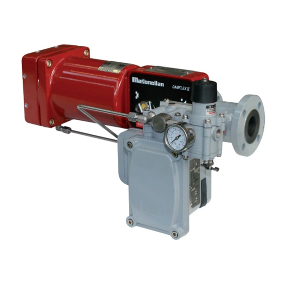
- Page 1 Instructions No ES 50004-250 E Rev. B 08/97 Masoneilan 8013 series Electropneumatic positioner Instructions used with 35002 series Camflex II and 30000 series Varimax control valves Masoneilan Masoneilan...
-
Page 2: Description And Operation
Preliminary remarks Moreover, before initiating any operation on this positioner the following should be read : 1. Note the serial number for future reference. a) operating instructions pertaining particularly to 2. The positioner is fitted with a powerful magnet : do installation. -
Page 3: Split-Range Operation
Direct action Changing of action With direct positioner action, an increase in the output a) Reverse the positions of the coil leads on the signal produces a force on the beam moving the flapper terminal board (see Instruction sheet No ES to cover the nozzle. - Page 4 Serial connecting The table of Figure 3 summarizes these two operating modes. Positioners model 8013 can be modified on the field to operate two split-ranging valves, selecting the proper To calibrate a positioner for split-ranging operation, cam lobe. proceed as indicated in chapter “Calibration” considering that the connection of the controller on each positioner is Parallel connecting performed as indicated in the table.
- Page 5 Force Balance Spring LOCKNUT (7) Position ADJUSTING SCREW (6) Direct Action BIASING Below Beam SPRING (52) FORCE BALANCE SPRING (8) SPRING LEVER (10) LOCKNUT (11) HOOKING Reverse Action SCREW (12) Below Beam Figure 5 2. Be sure that the coil and the terminal board are Cam mounting and orientation (Figures correct for the input signal characteristics.
- Page 6 The supply connection of the air filter-regulator model 77-4 is 1/4” NPT. Adjust the output pressure of the air Selection of Proper Line on Cam Lobe for filter-regulator to the pressure indicated on the serial Alignment with Cam Follower Bearing plate of the actuator.
-
Page 7: Maintenance
Air-to-open valve 12. Adjust signal to proper value corresponding to valve closed position. 5. Shut-off supply pressure. Valve plug should be 13. Adjust the biasing spring (52) so that the valve plug seated. will lift off the seat at the proper closing milliamp 6. - Page 8 PARTS REFERENCE Ref. Ref. Ref. Part Name Part Name Part Name Cover Screw Relay Biasing Spring Emblem Mounting Screw (Relay) Mounting Screw (relay) Cover Screw Relay Cap Mounting Screw Serial Plate Diaphragm S/A Magnet S/A Force Balance Spring Lever Bellofram Plate S/A Adjusting Screw Release Spring Gasket...
-
Page 9: Troubleshooting
Flexure strip replacement Alignment Rod 1/8”(3,175 mm) Dia. Mounting Screw 1. Remove positioner cover and disconnect coil leads Biasing Spring Adjusting Screw from the terminal board. Disengage the end of the Coil Screw (45) Biasing Spring Bracket (39) force balance spring (8) from the adjusting Biasing Spring (52) screw (6). - Page 10 8. Coil stop adjusted to allow approximately (0.8 mm) Electrical circuit (1/32”) flapper travel in front of nozzle. After checking pneumatic circuit, the electrical circuit 9. All mechanism components fastened firmly as should be checked with an ohmmeter as follows: required.
- Page 11 DISTRIBUTOR E.P. & S. - FRANCE 24 bis rue de Picpus 75012 PARIS Tel: +33 (0) 762 682 291 Tel: +33 (0) 650 590 965 ventes@fr-eps.com E.P. & S. - CAMEROON Immeuble Carré d’Or Rue Soppo Priso Côté Chococho, Bonapriso DOUALA Tel: +237 6 52 12 70 95 Tel: +33 (0) 782 006 276...
Need help?
Do you have a question about the Masoneilan 8013 Series and is the answer not in the manual?
Questions and answers