Table of Contents
Advertisement
Quick Links
Advertisement
Table of Contents

Related Manuals for Dresser Masoneilan SVI II AP-2


Summary of Contents for Dresser Masoneilan SVI II AP-2
- Page 2 Warranty Items sold by Dresser® are warranted to be free from defects in materials and workmanship for a period of one year from the date of shipment provided said items are used according to Dresser recommended usages. Dresser, Inc. reserves the right to discontinue manufac- ture of any product or change product materials, design or specifications without notice.
-
Page 3: Safety Symbols
Safety Information This section provides safety information including safety symbols that are used on the SVI II AP and the safety symbol definition. Important - Please Read Before Installation! Safety SVI II AP instructions contain DANGER, WARNING, and CAUTION Symbols labels and Notes, where necessary, to alert you to safety related or other important information. -
Page 4: Svi Ii Ap Product Safety
Before using these products with fluids other than air or for non- industrial applications, consult Dresser, Inc. This product is not intended for use in life support systems. Under certain operating conditions, the use of damaged instruments could cause a degradation of the performance of the system which may lead to personal injury or death. -
Page 5: Table Of Contents
Contents Safety Symbols ..........i Safety Information . - Page 6 Masoneilan Dresser SVI II AP Quick Start Guide SVI II AP Maintenance ........14 Repair .
- Page 7 Calibration ..........28 Auto Tune .
- Page 8 Masoneilan Dresser SVI II AP Quick Start Guide...
-
Page 9: Section 1 Installation And Set Up
Installation and Set Up ® Introduction The SVI II AP (Smart Valve Interface) is the next generation of Masoneilan’s intelligent digital valve positioners. The SVI II AP is a compact, industrial tough, high performance, digital valve positioner that combines a local display with remote communication and diagnostic capabilities. -
Page 10: Using The Quick Start Guide
Masoneilan Dresser SVI II AP Quick Start Guide SVI II AP Assembled SVI II AP Cover Pneumatic Train and Cover (I/P Module, Relay) Manifold Electronics Module Relay Figure 2 SVI II AP Components Using the The SVI II AP Quick Start Guide is intended to help an experienced... -
Page 11: Mounting The Svi Ii Ap
Installation and Set Up Mounting the SVI II AP Table 1 SVI II AP Installation Steps Step No. Procedure Reference Install the Remote Position Sensor, if See page 4 for instructions. necessary. Connect the pneumatic tubing to the See page 7 for instructions. SVI II AP. -
Page 12: Necessary Precautions
Masoneilan Dresser SVI II AP Quick Start Guide Necessary Precautions To avoid injury or the process being affected when installing or replacing a positioner on a control valve, ensure that: If the valve is located in a hazardous area make sure the area has been certified as “safe”... -
Page 13: Installation Procedure
Installation and Set Up Installing the SVI II AP Remote Position Sensor Comply with national and local explosive atmosphere regulations. Before carrying out any work on the device, power off the instrument or make sure that the locale conditions for potentially explosive atmosphere permit the safe opening of the cover. - Page 14 Masoneilan Dresser SVI II AP Quick Start Guide Table 2 Remote Position Sensor Turnbuckle Length Actuator Size Stroke Turnbuckle Length 0.5 - 0.8 inch 2.90 inch >0.8 – 1.5 inch 2.90 inch >1.5 – 2.5 inch 2.90 inch 0.5 - 0.8 inch 5.25 inch...
-
Page 15: Connecting The Tubing And Air Supply
Installation and Set Up Connecting the Tubing and Air Supply Connecting The last step in hardware installation for the SVI II AP is to connect the the Tubing air supply to the positioner. This section describes the process for and Air connecting the tubing and air supply to a single and double acting positioner. -
Page 16: Single Acting Positioner
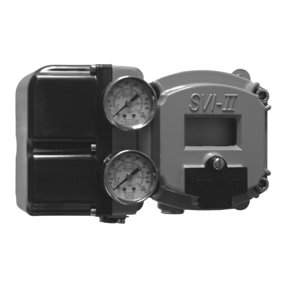
Masoneilan Dresser SVI II AP Quick Start Guide Single Acting Positioner The supply and output connections for the SVI II AP, located on bottom of the pneumatic block, are tapped 1⁄4 inch NPT. Output is toward the front, supply is toward the back. Two pressure gauges, output on top, supply on bottom, are located on the front of the pneumatic block. -
Page 17: Double Acting Positioner
Installation and Set Up Connecting the Tubing and Air Supply Double Acting Positioner ← I)” to the inlet port of the actuator and Connect Output 1, labeled “( ← II)” to the opposing actuator port (see connect Output 2 labeled “( Figure 5 below for double acting ports. -
Page 18: Wiring The Svi Ii Ap
Masoneilan Dresser SVI II AP Quick Start Guide Wiring the In order for the SVI II AP to communicate the positioner data the SVI II SVI II AP AP must be physically connected to a HART communication. The procedure below outlines wiring the SVI II AP. -
Page 19: Svi Ii Ap Setups
Installation and Set Up Wiring the SVI II AP Capacitance of the signaling circuit must not exceed 0.26 microfarads or 0.10 microfarads with high series resistance. Cabling must be shielded to prevent electrical noise that would interfere with the HART tones, with the shield grounded. -
Page 20: Grounding Practices
Masoneilan Dresser SVI II AP Quick Start Guide Grounding Practices To ensure proper grounding make sure that case, signal, and ground connections are made in compliance with the plants normal grounding practices. Any point in the loop can be referenced to ground, but there must never be more than one ground point. - Page 21 Installation and Set Up Wiring the SVI II AP Note: Improperly or inadequately grounded installations can cause noise or instability in the control loop. The internal electronic components are isolated from ground. Grounding the case is unnecessary for functional purposes but grounding the case may be necessary to conform to local codes.
-
Page 22: Svi Ii Ap Maintenance
Masoneilan Dresser SVI II AP Quick Start Guide SVI II AP The SVI II AP was designed based on a modular concept. All Maintenance components are interchangeable allowing for easy, quick component swapping. The only maintenance procedures recommended for the SVI II AP are:... -
Page 23: Display Cover Removal And Installation
Installation and Set Up SVI II AP Maintenance Display Cover Removal and Installation The cover with display (shown in Figure 8 below) is an option for the SVI II AP. If you have an SVI II AP with a solid cover and would like to upgrade to a display cover, follow the instructions below for removal and installation. - Page 24 Masoneilan Dresser SVI II AP Quick Start Guide Using the 3mm hex key, remove the screw from the lower left corner, connecting the terminal board to the SVI II AP housing. Connect the cable from the display into the LCD connector on the terminal board.
-
Page 25: Section 2 Check Out, Configuration And Calibration
Check Out, Configuration and Calibration Overview This section provides the calibration procedures to ensure proper valve positioning. Operational checkout, configuration and calibration procedures are described using an SVI II AP that has a display with pushbuttons. Note: You should perform all procedures in this section before putting the SVI II AP into operation. -
Page 26: Verify Mounting And Linkage Adjustment
Masoneilan Dresser SVI II AP Quick Start Guide Verify Mounting and Linkage Adjustment Inspect the mounting and make any needed adjustments before running the positioner and checking the digital configuration. Checking the Magnet There are two methods of checking the SVI II APmagnet: Perform a visual inspection Use ValVue 2.4 to check the magnet... -
Page 27: Using Valvue 2.4 To Check Magnet Position
Check Out, Configuration and Calibration Check Out Procedures Clockwise to Close Clockwise to Open ° Magnet Axis with Valve Closed Figure 10 Magnet Orientation for 90 Degree Valve Rotation with Valve Closed Table 4 Reciprocating Valve Mounting Hole Selection Turnbuckle Actuator Size Stroke Mounting Hole... -
Page 28: Checking The Air Supply
Masoneilan Dresser SVI II AP Quick Start Guide Run ValVue 2.4. Select the installed positioner from the list of Connected Devices. Select the: ”Check” tab to view the current operating conditions of the selected positioner. Read Raw Sensor Data. When the valve is closed the value should be between –... - Page 29 Check Out, Configuration and Calibration Check Out Procedures Table 5 SVI II AP Models and Functionality Positioner Model Number Available Functionality SVI II AP-2 SVI II AP-3 4 - 20 mA Input Setpoint Display/ Pushbuttons Optional Optional Remote Mount Input Process Variable 1 - 5 VDC SW #1 and #2 Optional...
-
Page 30: Making Connections To The Terminal Board
Masoneilan Dresser SVI II AP Quick Start Guide Making Connections to the Terminal Board Each terminal block on the terminal board has a cage clamp connector. One side of the connector has the actual connection for the wire, with a lever at the top. If there is an option present that is not properly... -
Page 31: Pushbutton Locks And Configuration-Lock Jumper
Check Out, Configuration and Calibration Operational Checkout Pushbutton Locks and Configuration-Lock Jumper Before performing any of these functions with the local display you must first ensure that the pushbuttons are placed in the unlocked mode using ValVue 2.4 Lite. The positioner is provided in the unlocked mode. See ValVue 2.4 documentation for more details. -
Page 32: Configuration
Masoneilan Dresser SVI II AP Quick Start Guide To power up the SVI II AP: Loosen the four (4) cover screws and remove the cover of the SVI II AP. Connect the +⁄- terminals to the current source + to + and - to -. See Figure 11 on page 21. -
Page 33: System Requirements
Check Out, Configuration and Calibration Configuration System Requirements ValVue Lite runs on IBM compatible computers. Minimum requirements for all versions of ValVue software are Windows 2000, and XP, 16 MB RAM, a serial or USB port connected to a HART modem, and a CD-ROM drive. -
Page 34: Pushbuttons
Masoneilan Dresser SVI II AP Quick Start Guide Pushbuttons The local pushbuttons are located behind a hinged cover, directly below the display window. To open the cover loosen the screw and swing the cover down. Always re-fasten the cover after use to protect the pushbuttons from environmental contamination. -
Page 35: Configuration With Pushbuttons
Check Out, Configuration and Calibration Configuration Configuration with Pushbuttons Prior to changing the SVI II AP configuration, check the existing configuration. Viewing Configuration Data To view SVI II AP configuration data: Access the VIEW DATA menu from the MANUAL menu by pressing the “+”... -
Page 36: View Data Settings
Masoneilan Dresser SVI II AP Quick Start Guide VIEW DATA Settings Table 7 VIEWDATA Settings Typical Setting Optional Setting SINGLE DOUBLE LINEAR EQUAL 30 EQUAL 50 QUICK 50 CUSTOM CAMFXEQ 0.00 2.00 TS OFF TS ON 4.00 4.00 SIG LO SIG LO 20.00... -
Page 37: Auto Tune
Check Out, Configuration and Calibration Calibration Auto Tune To auto tune the SVI II AP: Press * to begin the autoTUNE procedure. This takes 3 to 10 minutes and strokes the valve in large and small steps to set the PID parameters for best positioning response. When autoTUNE proceeds, numerical messages display, indicating the procedure is working. - Page 38 Masoneilan Dresser SVI II AP Quick Start Guide any key Normal Cycling View Normal Manual View ERR CLR ERR Menu Data View View any key Manual Mode Instant Errors Data Cycling Menu Action Menu Menu <value> View Normal Manual View ERR...
-
Page 39: Check-Out With A Hart Handheld Communicator
Check Out, Configuration and Calibration Calibration Check-out with a HART Handheld Communicator If the SVI II AP is not equipped with optional push buttons and local display the checkout and configuration is performed using the standard HART communications interface. onnect the HART Handheld Communicator (HHC) to the SVI II AP as shown in Figure 14 below. - Page 40 Masoneilan Dresser SVI II AP Quick Start Guide Proceed with the following steps: Press NEXT Field device has more status available Press NEXT Ignore next 50 occurrences of status? Press YES Change to MANual mode -> Scroll to line 6 EXAMINE, press Scroll down to 5 read status.
-
Page 41: Appendix A Specifications And References
Specifications and References Physical and This section provides the physical and operational specifications for the Operational SVI II AP. Specifications Table 8 Environmental Specifications Operating Temperature Limits -58 deg. F to 185 deg. F (-50 deg. C to 85 deg. C) Storage Temperature Limits -58 deg. - Page 42 Masoneilan Dresser SVI II AP Quick Start Guide Table 9 Operational Specifications * Specifications are subject to change without notice Accuracy +/- 0.5% (typical +/-0. 10% or less) Full Span Hysteresis and Deadband +/- 0.3% Full Span Repeatability +/- 0.3% Full Span Conformity +/- 0.5% Full Span...
- Page 43 Specifications and References Physical and Operational Specifications Table 10 Input Signal, Power, and Display Specifications Power Supply Taken from 4-20mA control signal Compliance Voltage Rating 9.0 Volts at 20 mA, 11.0 Volts at 4.0 ma Minimum Current Signal to Start Up 3.2 mA Minimum Input Span for Split Range Operation Upper Range Value for Split Range Operation...
- Page 44 Masoneilan Dresser SVI II AP Quick Start Guide Table 12 System Connectivity HART Physical Device Type Actuator; HART device type 7 DD Registered with HART Communication Yes, available through HART Communication Foundation Foundation AMS Driver for Fisher-Rosemount Asset ValVue 2 AMS SNAP-ON application available...
- Page 45 Specifications and References Physical and Operational Specifications Table 14 Pneumatics Double Acting Standard Flow Air Supply Dry, oil-free, 5 micron filtered air see ISA S7.3 Action Output 1 increases with increasing I/P signal. Output 2 decreases with increasing I/P signal. Supply Pressure 20 - 150 psi max.
-
Page 46: Hazardous Location Installation
Masoneilan Dresser SVI II AP Quick Start Guide Series Identification SVI2 AP-abcdefgh a Style 1,2,3 1. ES Version - EZ Smart 2. SD Version - Standard Diagnostics 3. AD Version - Advanced Diagnostics b Pneumatic Train 1,2 1. Single Acting 2. - Page 47 The SVI-II AP is manufactured by: Masoneilan/DRESSER 85 Bodwell Street Avon MA – 02322 – USA Copyright 2005 . This document and all information herein is the property of Dresser Inc. Description Date Initial Release 16 Aug 05 Revised model code, min XP...
- Page 48 Masoneilan Dresser SVI II AP Quick Start Guide 2 GENERAL REQUIREMENTS !WARNING! Failure to adhere to the requirements listed in this manual may cause loss of life and property. Installation and maintenance must be performed only by qualified personnel. Area Classification, Protection Type, Temperature Class, Gas Group, and Ingress protection must conform to the data indicated on the label.
- Page 49 Name and address of could cause an explosion ATEX Logo manufacturer if the cover is opened. Masoneilan/DRESSER AVON MA USA DO NOT OPEN EVEN WHEN ISOLATED WHEN Certificate Number FLAMMABLE / DUST ATMOSPHERES ARE PRESENT ZELM 05ATEX0280X ©...
- Page 50 Masoneilan Dresser SVI II AP Quick Start Guide 5.2 Category II 1 (Zone 0) For operation in hazardous area category II 1, over-voltage protection of the electrical connections need to be installed according to EN 60079-14 For operation in hazardous area category II 1 the ambient temperature needs to be lowered according to the requirements of EN 1127-1 (reduction factor of 80% ).
- Page 51 5.4 Description of SVI2-1 Marking Category, types of protection and gas group designations Name and address of manufacturer Certificate Number Requirement to Masoneilan/DRESSER AVON MA USA follow certified Maximum Surface Temperature installation ZELM 05ATEX0280X for Dust at Ta=85°C drawing Intrinsically Safe Installed per ES-699...
- Page 52 ENTITY AMBIENT PARAMETERS INTRINSICALLY SAFE WHEN INSTALLED PER ES-699 TEMPERATURE Ui=6.5 Volts Ii=10.5 mA Ci=0 Li=0 Pi=68mW LIMITS SERIAL NUMBER INSIDE ENCLOSURE Masoneilan / DRESSER NAME AND ADDRESS OF AVON MA, 02322 MANUFACTURER THE SERIAL SERIAL: YAyywwxxxx NUMBER IS Serial Number Label...
- Page 53 Specifications and References Hazardous Location Installation Intrinsically Safe Installation Wiring Requirements Each intrinsically safe cable must include a grounded shield or be run in a separate grounded metal conduit. ES-699 Rev F Page 7 of 10 A-13...
- Page 54 Masoneilan Dresser SVI II AP Quick Start Guide Notes for Intrinsically Safe Installation 1. HAZARDOUS LOCATION Refer to the device label for the description of the environment in which the device may be installed. 2. FIELD WIRING Intrinsically Safe wiring must be made with grounded shielded cable or installed in grounded metal conduit.
- Page 55 Specifications and References Hazardous Location Installation 5. SVI-II AP (+) and (-) PV 1-5VDC Terminals The Process Transmitter and the SVI-II AP PV Input are both barrier protected. The transmitter 4 to 20 mA signal is converted to 1 to 5 Volts at the Transmitter barrier. The 1 to 5 volt signal is monitored by the DCS and used by the SVI-II AP for the embedded process controller.
- Page 56 Masoneilan Dresser SVI II AP Quick Start Guide 10. Use in dust atmosphere Dust-tight conduit seal must be used when installed in dust hazard environments. 11. A device which has previously been installed without an approved IS barrier must NEVER be used subsequently in an intrinsically safe system.
- Page 57 FAX: +33-1-4904-9010 FAX: +44-1695-52601 MEXICO DRESSER PRODUITS INDUSTRIELS S.A.S., DRESSER VALVE DE MEXICO, S.A. DE C.V. DI U.K. LTD. MASONEILAN CUSTOMER SERVICE CEN- HENRY FORD NO. 114, ESQ. FULTON UNIT 4, SUITE 1.1, NOBEL HOUSE FRACCIONAMIENTO INDUSTRIAL SAN NICO- GRAND UNION OFFICE PARK...
Need help?
Do you have a question about the Masoneilan SVI II AP-2 and is the answer not in the manual?
Questions and answers