
Related Manuals for Dresser Masoneilan 4700P


Summary of Contents for Dresser Masoneilan 4700P
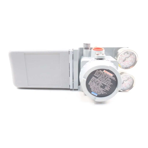
- Page 1 Instruction ES2007 4/98 Corrosion Resistant Positioner Instructions Models 4700P and 4700E For complete listing of spare parts, refer to Masoneilan publication FS2007...
-
Page 2: Table Of Contents
Items sold by Dresser Masoneilan are warranted to be free tion. Installation should be in accordance with local and from defects in materials and workmanship for a period national compressed air and instrumentation codes. -
Page 3: General Description And Operation
Instruction ES2007 4/98 Models 4700P and 4700E Model 4700P and 4700E Positioner Numbering System Signal Span Mounting Type 0. 4-20 mA 0. Rotary P. Pneumatic 1. 3-15 psi 1. Reciprocating E. Electropneumatic (12 psi) 2. 6-30 psi (24 psi) General Description and Operation exhaust port. -
Page 4: Installation
Instruction ES2007 4/98 Models 4700P and 4700E Optional Bypass Valve or reverse action (increasing instrument signal produces a decrease in output pressure). See Figures 2 and 3. (4700P, Direct Acting Model only) Note that the 4700E is not available with reverse action, During normal operation, the instrument signal is applied hence if the application demands reverse action, a 4700P directly to the positioner diaphragm and the regulated... - Page 5 Instruction ES2007 4/98 Models 4700P and 4700E Direct Positioner Action Reverse Positioner Action 4700P Only yyy y Diaphragm Pilot Supply Exhaust Spring yy yy yy yy yy yy Bypass Pilot Lever Feedback Valve Plug Spring Figure 2 - Rotary Direct Positioner Action Reverse Positioner Action 4700P Only Lever...
- Page 6 Instruction ES2007 4/98 Models 4700P and 4700E 87/88 Actuator Mounting Parts Reference 87/88 Ref. No. Description Ref. No. Description Ref. No. Description Clamp Rod Tubing Screw, .312-18 x 1.25 Turnbuckle Screw Positioner Washer, Shakeproof Clevis Male Connector Ring, Retaining Back Lever Cap Screw Cap Screw Clevis Pin...
- Page 7 Instruction ES2007 4/98 Models 4700P and 4700E 87/88 Actuator Mounting 4700P and 4700E on Series 87/88 Actuators. 5. Check Figure 5 for proper mounting location for posi- tioner on bracket. 1. Using screws (113) and lockwashers (114), mount bracket (115) on actuator with opening located to the right 6.
- Page 8 Instruction ES2007 4/98 Models 4700P and 4700E 87U/88U Actuator Mounting 4700P and 4700E on Series 87U/ 88U Actuators. 1. Mount lever (1U) between two jam nuts (11U) on valve stem. 2. Attach turnbuckle screw (101) to lever (1U). 3. Assemble jam nut (107) to clevis (102). Assemble clevis to turnbuckle screw (101).
- Page 9 Instruction ES2007 4/98 Models 4700P and 4700E Positioner Mounting and Orientation ® ™ ® Camflex II, Varimax, MiniTork II, Ball II, and HPBV (Figures 7, 8, 9, and 10) The positioner is mounted to an intermediate plate (171) by two screws (29) and lockwashers (30) with the gauges nearest the actuator on Camflex and Varimax and with gauges away from actuator on Ball II, MiniTork II, and HPBV.
- Page 10 Instruction ES2007 4/98 Models 4700P and 4700E Ball II and MiniTork II Air to Open Air to Close (For detail of Positioner Mounting, see Figure 7) Figure 9 High Performance Butterfly Valve (HPBV) Air to Open Air to Close (For detail of Positioner Mounting, see Figure 7) Figure 10...
- Page 11 Instruction ES2007 4/98 Models 4700P and 4700E Pneumatic Installation Note: The output and supply connections for the 4700E/P Caution: Do not use pipe thread sealant tapes on are different from those on the 4600A. pneumatic fittings, as it tends to shred small particles which can cause instrument malfunction.
- Page 12 Instruction ES2007 4/98 Models 4700P and 4700E PLUG SUPPLY SUPPLY DIR SUP REV EXH OUTPUT DIR EXH REV SUP VENT OUTPUT 4700E Direct Action SIGNAL SUPPLY SUPPLY INSTRUMENT DIR SUP REV EXH OUTPUT DIR EXH REV SUP OUT VENT OUTPUT 4700P Direct Action SIGNAL VENT...
- Page 13 Instruction ES2007 4/98 Models 4700P and 4700E Electrical Installation of 4700E Electrical connections should be made as shown in Figure 12. The terminals will accept wire sizes up to AWG 14. WARNING: The positioner must be installed in accordance with local and national codes of prac- The loop controller driving the positioner must be capable tice in both general purpose and hazardous area of supplying 4-20 mA with an output voltage compliance of...
- Page 14 Instruction ES2007 4/98 Models 4700P and 4700E Hazardous Area Installations Installation must be in accordance with the current edition of the Canadian National Electrical Code Part I, any appli- The positioner is available in versions suitable for use in cable local codes and manufacturer’s instructions. hazardous areas.
- Page 15 Instruction ES2007 4/98 Models 4700P and 4700E...
- Page 16 Instruction ES2007 4/98 Models 4700P and 4700E...
- Page 17 Instruction ES2007 4/98 Models 4700P and 4700E...
-
Page 18: Calibration
Instruction ES2007 4/98 Models 4700P and 4700E Mounting Cam Coupling Changing Lever S/A Orientation (see pages 27 - 29) (Figure 19 & 20) If lever S/A (3) must be changed, remove screw (28) The cam coupling (34), used on rotary actuators, is posi- and washer (27), and cam (26) from cam shaft. -
Page 19: Cam Lobe Change
Instruction ES2007 4/98 Models 4700P and 4700E end of signal range, after making zero adjustment, Air to Open/Direct Acting Positioner (Figure 19 & 20) decrease signal below low end of signal range and 1. Shut off supply pressure and signal to positioner. slowly increase signal to ensure valve plug lifts off seat Valve is now closed and cam (26) is at low signal line at desired signal. -
Page 20: Field Mounting And Complete Calibration
Instruction ES2007 4/98 Models 4700P and 4700E 2. With cam at low signal line remove screw (28) and Air to Open/Direct Acting Positioner (Figure 19 & 20) washer (27). Note the relative position of the cam 1. Do not connect air supply or signal to the positioner. lobe being changed and then remove the cam (26). - Page 21 Instruction ES2007 4/98 Models 4700P and 4700E selection. Secure cam (26) to cam holder (36) with 7. Connect air supply and signal to positioner. Connect washer (27) and screw (28). Tighten screw (28) while positioner output to valve actuator. Refer to connec- holding the cam (26).
- Page 22 Instruction ES2007 4/98 Models 4700P and 4700E Field Mounting and Complete 4. Disconnect the independent regulated air line and connect the positioner output line to the actuator. Calibration Reciprocating Valves Connect supply pressure and signal to the positioner. using 87/88 Actuators 5.
-
Page 23: Positioner Action Change
Instruction ES2007 4/98 Models 4700P and 4700E approximately aligned with positioner case raised From Air to Open/Direct to Air to Open/Reverse reference line. Secure cam to shaft using washer (27) 1. Perform Steps 1 and 2 from “Cam Lobe Change” and screw (28). - Page 24 Instruction ES2007 4/98 Models 4700P and 4700E Pilot (Figure 18) 5. Remove cap screws (10) and separate body S/A from the case S/A. To clean or replace deteriorated parts, the valve must be 6. Remove the diaphragm assembly (9), and reducer isolated from process.
- Page 25 Instruction ES2007 4/98 Models 4700P and 4700E Bypass Valve Option (4700P Only) 5. Reinstall vent plug, instrument gauge, and air connec- tions. Assembly to Positioner (Figure 21) Disassembly Note: It may be necessary to remove positioner from 1. To remove from positioner, reverse assembly steps 5 valve to assemble bypass.
- Page 26 Instruction ES2007 4/98 Models 4700P and 4700E Troubleshooting The following conditions must exist to ensure satisfactory In case of malfunction, check following in order given: operation of the positioner: 1. Check zero adjustment and adjust the zero nut (4B) 1. The valve must be properly mounted in the line so that if necessary.
-
Page 27: Cam Lobe Selection And Lever Arm Orientation
Instruction ES2007 4/98 Models 4700P and 4700E Cam Lobe Selection and Lever Arm Orientation Camflex II and Varimax Valve Positioner Range and Action Action Characteristic Lobe Direct 0-100 % Lin 0-100 % Perc 0-50 % Lin Right 50-100 % Lin Reverse 0-100 % Lin Open... - Page 28 Instruction ES2007 4/98 Models 4700P and 4700E MiniTork II Valve Positioner Range and Action Action Characteristic Lobe Direct 0-100 % Perc 0-50 % Perc Right 50-100 % Perc 75° Reverse 0-100 % Perc Open 0-50 % Perc Left 50-100 % Perc Direct 0-100 % Perc 0-50...
- Page 29 Instruction ES2007 4/98 Models 4700P and 4700E 87/88 Actuator and 87U/88U Actuator Valve Positioner Range and Action Action Characteristic Lobe Direct 0-100 % Lin 0-100 % Perc 0-50 % Lin Right 50-100 % Lin Reverse 0-100 % Lin Open 0-100 % Perc 0-50 % Lin Left...
- Page 30 Instruction ES2007 4/98 Models 4700P and 4700E Reference Line Follower Sector in use Rotary Reciprocating Reducer plate for 6-30 only. Mount rounded side of reducer plate towards diaphragm. Figure 19 - 4700P 3-15 and 6-30 Ranges...
-
Page 31: Parts Reference
Instruction ES2007 4/98 Models 4700P and 4700E Parts Reference 4700P 3-15 and 6-30 Range Ref. No. Description Ref. No. Description Body S/A Case S/A Washer Lever S/A Pan Head Screw Spring End Socket Head Screw Cam Follower Lockwasher Zero Nut Gasket Zero Lock Nut Socket Head Screw... - Page 32 Instruction ES2007 4/98 Models 4700P and 4700E Rotary Reciprocating Figure 20 - 4700E...
- Page 33 Instruction ES2007 4/98 Models 4700P and 4700E Parts Reference 4700E Ref. No. Description Ref. No. Description Body S/A Case S/A Washer Lever S/A Pan Head Screw Spring End Socket Head Screw Cam Follower Lockwasher Zero Nut Gasket Zero Lock Nut Socket Head Screw Spring, Feedback Lockwasher...
- Page 34 Instruction ES2007 4/98 Models 4700P and 4700E Signal Supply Output Parts Reference Ref. Description Vent Plug Screw 8-32 x 1.25 SEMS Bypass S/A O-ring O-ring Valve, Bypass Ring, Retaining O-ring Figure 21 - Bypass Option...
-
Page 35: Specification Data
Instruction ES2007 4/98 Models 4700P and 4700E Specification Data type cam feedback, pneumatic, 4700P force balanced; electropneumatic positioner uses current to deadband <0.2% of span pneumatic converter to generate pneumatic operating signal hysteresis <0.2% of span action direct: increasing signal increases output repeatability within 0.2% of span... - Page 36 Masoneilan is an international leader in the design, manufacture, and support of final control elements and solutions for efficient process automation. Masoneilan is an integral part of Dresser Industries’ Valve & Controls Division (DVCD), which also includes the Nil-Cor and Industrial Valve Operations.
Need help?
Do you have a question about the Masoneilan 4700P and is the answer not in the manual?
Questions and answers