Advertisement
USERS' MANUAL
SYSTEM
Via Aurelia Ovest, Km. 383 - 54100 Massa (MS) - ITALY - Tel.: +39 0585 8364 - Fax: +39 0585 833880 - www.globaljig.it
Società unipersonale sotto la direzione e controllo della Bellini Srl. -
Capitale sociale € 100.000,00 i.v.
Iscritta al Reg. Imprese di Massa Carrara al N° 01064230459
Advertisement
Table of Contents

Related Manuals for Globaljig SYSTEM


Summary of Contents for Globaljig SYSTEM
- Page 1 USERS’ MANUAL SYSTEM Via Aurelia Ovest, Km. 383 - 54100 Massa (MS) - ITALY - Tel.: +39 0585 8364 - Fax: +39 0585 833880 - www.globaljig.it Società unipersonale sotto la direzione e controllo della Bellini Srl. - Capitale sociale € 100.000,00 i.v.
- Page 2 USERS’ MANUAL SYSTEM Year of Manufacture: .......
-
Page 3: Table Of Contents
USER’S MANUAL CONTENTS SYSTEM/VECTOR INTRODUCTION ............5 SAFETY ..............7 TECHNICAL CHARACTERISTICS AND DATA ....9 TRANSPORT AND UNPACKING .........11 INSTALLATION ............13 START-UP ..............17 CONTROLS ...............19 OPERATIONS ............21 MAINTENANCE............23 10. REPAIRS / SPARE PARTS.........25 11. DRAWINGS ..............27 12. DEMOLITION ............35... -
Page 4: Introduction
The Manual explains how to use the Machine, and provides instructions and useful tips to ensure the best possible performance. The SYSTEM straightening bench with VECTOR arm has been designed and manufactured to guarantee long life and to ensure safe operations. -
Page 5: Safety
Tampering with, or modifying, the safety devices is in violation with European Safety Standards. The SYSTEM unit can only be used indoors. It must be installed by Qualified Personnel and in compliance with the instructions contained in this Manual. -
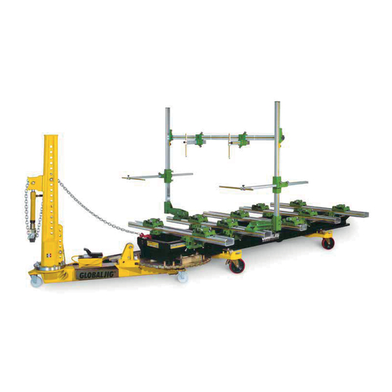
Page 6: Technical Characteristics And Data
3.1. CHARACTERISTICS • Name of the Machine: SYSTEM bench with VECTOR arm is the market name of this Machine, which is a MECHANICAL ARM. The force of this machine derives from the combined application of a link chain with a hydraulic cylinder. - Page 7 The serial number and CE labelling are reported on the label indicated in the figure below. This label is positioned on the: - front crossbeam of the SYSTEM bench - Vector work arm close to the engage/release lever The identification data are reported on the fixed label secured to the Machine structure: never remove, alter or damage these labels.
-
Page 8: Transport And Unpacking
Take a good look at the package since the Manufacturer cannot be held responsible for any damage to the equipment derived from shipping. Globaljig International S.r.l. guarantees the suitability of the materials used in its packaging and the best procedure for setting the goods in these packages. -
Page 9: Installation
MAXIMUM WEIGHT CAPACITY OF THE BENCH SYSTEM ON WHEELS Kg 3100. 5.2. HANDLING the SYSTEM bench and VECTOR arm (see page 19) Once the work area has been selected, move the package into position with a forklift or lift truck. - Page 10 USER’S MANUAL CHAPTER 5 SYSTEM/VECTOR 5.3. UNPACKING Remove the lid and open one side of the crate. Withdraw all the wooden parts used to lock the unit in place during shipping. Withdraw the vertical body and then push out the horizontal body on its own wheels.
- Page 11 USER’S MANUAL CHAPTER 5 SYSTEM/VECTOR 5.4. ASSEMBLY horizontal body delivered preassembled. At this point the tool- holder must installed simply inserting it as indicated in fig. 05 - 02. Then remove the large half ring from its housing and install the vertical body on the flange.
- Page 12 USER’S MANUAL CHAPTER 5 SYSTEM/VECTOR 5.5. ASSEMBLY OF THE HYDRAULIC CYLINDER The components involved are shown in fig. 05 - 05 1) Male connection 2) Hydraulic cylinder 3) Female connection with fork Insert the male connection in its position as shown in ...
-
Page 13: Start-Up
USER’S MANUAL CHAPTER 6 SYSTEM/VECTOR 6. START-UP 6.1. COUPLING TO THE BENCH The vector can be inserted and secured to the Bench from both the front and side. The vector is pushed in from the front, rolling on the three wheels,... -
Page 14: Controls
USER’S MANUAL CHAPTER 7 SYSTEM/VECTOR 7. CONTROLS 7.1. POSITIONING THE VECTOR manual engage/disengage lever on the horizontal body inside the notched plate is used to secure the Vector in the best position for pulling. Positioning is then performed by moving the lever as shown in fig. - Page 15 USER’S MANUAL CHAPTER 7 SYSTEM/VECTOR 7.3. APPLYING THE PULLING CHAIN One end of the 3-meter-long, high resistance steel link chain is free while the other end is fit with a pulling hook. 7.4. DIRECT PULLING Connect the pulling hook to the terminal secured...
-
Page 16: Operations
GLOBALJIG data sheet. • Determine what part of the body needs to be straightened. • Position the Vector on the SYSTEM Bench following the instructions in Chapter 06. Then arrange it to achieve the correct pulling direction by correctly positioning the snub pulley–chain on the axial wheels of the... -
Page 17: Maintenance
USER’S MANUAL CHAPTER 9 SYSTEM/VECTOR 9. MAINTENANCE Scheduled maintenance is limited to general cleaning of the Vector at the end of the work shift and after vehicle repair cycle. Maintenance of the hydraulic pump must only be performed by Qualified Personnel following the instructions given in the User’s Manual supplied with the pump itself. -
Page 18: Repairs / Spare Parts
10. REPAIRS / SPARE PARTS 10.1. REPAIRS A breakdown of the hydraulic system may depend on a pump or cylinder malfunction. To determine the cause of the defect, include all components in the troubleshooting procedure. Do not remove the components. Contact an Authorized Service Centre for assistance. -
Page 19: Drawings
USER’S MANUAL CHAPTER 11 SYSTEM/VECTOR 11. DRAWINGS 11.1. VECTOR WORKING ARM DIMENSIONS... - Page 20 USER’S MANUAL CHAPTER 11 SYSTEM/VECTOR 11.2. SYSTEM BENCH WORK AREA AND DIMENSIONS MODEL SYSTEM (4 m.) 1630 4020 6700 3340 SYSTEM (5 m.) 1630 5020 7700 3340...
- Page 21 USER’S MANUAL CHAPTER 11 SYSTEM/VECTOR 11.3. BREAKDOWN OF VECTOR WORK ARM...
- Page 22 USER’S MANUAL CHAPTER 11 SYSTEM/VECTOR 11.4. D435 - SYSTEM 5m BENCH...
- Page 23 USER’S MANUAL CHAPTER 11 SYSTEM/VECTOR 11.5. D436 - SYSTEM 4m BENCH...
- Page 24 USER’S MANUAL CHAPTER 11 SYSTEM/VECTOR 11.6. D445 – Series of bench feet with supports for anchoring to the floor...
- Page 25 USER’S MANUAL CHAPTER 11 SYSTEM/VECTOR 11.7. D448 – SERIES OF BENCH WHEELS...
-
Page 26: Demolition
CHAPTER 12 SYSTEM/VECTOR 12. DEMOLITION If the System/Vector is to be demolished, the User must remember that this operation must not create any Health or Environmental risks. The SYSTEM/VECTOR is considered special waste: • The components must be classified referring to the degree of disposal and recycling in compliance with current law. - Page 27 Capitale sociale € 100.000,00 i.v. Via Aurelia Ovest, Km. 383 - 54100 Massa (MS) - ITALY Tel.: +39 0585 8364 - Fax: +39 0585 833880 - www.globaljig.it Nessuna parte di questo documento può essere riprodotta né tradotta in altra lingua senza la preventiva autorizzazione scritta della società...
- Page 28 Società unipersonale sotto la direzione e controllo della Bellini Srl. Iscritta al Reg. Imprese di Massa Carrara al N° 01064230459 Capitale sociale € 100.000,00 i.v. Via Aurelia Ovest, Km. 383 - 54100 Massa (MS) - ITALY Tel.: +39 0585 8364 - Fax: +39 0585 833880 - www.globaljig.it...
Need help?
Do you have a question about the SYSTEM and is the answer not in the manual?
Questions and answers