
Subscribe to Our Youtube Channel
Related Manuals for Globaljig Super Rotax


Summary of Contents for Globaljig Super Rotax
- Page 1 USERS’ MANUAL Via Aurelia Ovest, Km. 383 - 54100 Massa (MS) - ITALY Tel.: +39 0585 8364 - Fax: +39 0585 833880 - www.globaljig.it...
- Page 2 USERS’ MANUAL Year of Manufacture: .......
- Page 3 Issue. Pag. INSTRUCTION MANUAL 08 / 2004 1 - 42 CHAPTERS : 1. INTRODUCTION 2. GENERAL SAFETY RULES 3. CHARACTERISTICS AND TECHNICAL DATA 4. FREIGHT AND UNPACKING 5. INSTALLATION 6. COMMISSIONING 7. CONTROLS AND SET UP 8. OPERATING 9. SAFETY DEVICE 10.
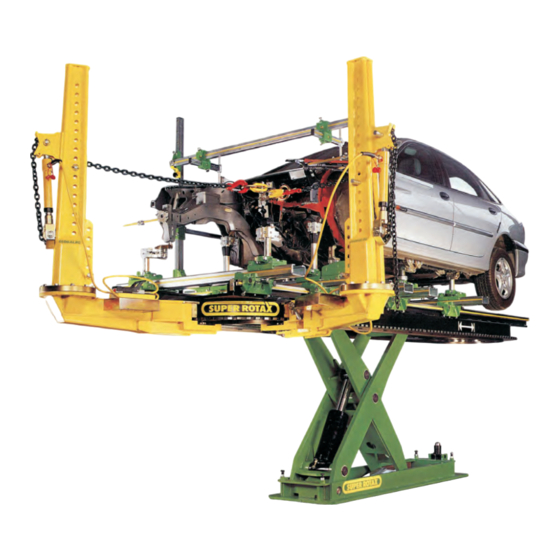
- Page 4 Manual until you understand completly all the instructions. This Manual explains how to use the Super Rotax, and includes instructions and suggestions for ensuring safe operations and optimum performance. The Super Rotax Lifting Bench (here after called “L.B.”) has been designed and manufactured to have a long working life and simple operation.
-
Page 5: General Safety Rules
Issue. Pag. INSTRUCTION MANUAL 08 / 2004 3 - 42 2. GENERAL SAFETY RULES Read this Manual carefully before proceeding to the installation and use of the Equipment. Only authorized and trained staff should be allowed to use this equipment. The “L.B.”... -
Page 6: Characteristics And Technical Data
3.1.2 INTENDED USE The Super Rotax equipment has been designed and built to be used as a Lifting – Bench (L.B.) for checking and realigning damaged vehicles. -
Page 7: Technical Data
All identification data are written on an alluminium plate positioned on the internal cross beam on the front of the bench, and it reports : the name of the manufacturer GLOBALJIG INTERNATIONAL. srl - Via Aurelia Ovest, Km 383 - 54100 Massa - ITALIA •... -
Page 8: Package Checking
E680 Control unit GLOBALJIG INTERNATIONAL. srl grants the quality of the packaging material and the best procedure concerning the correct location of the goods inside the packages. All operations of loading and unloading packages, must be carried out using specific procedures and methods as required by Health and Safety Regulations. -
Page 9: Installation
Issue. Pag. INSTRUCTION MANUAL 08 / 2004 7 - 42 5. INSTALLATION The installation of the L.B. must be carried out by trained personnel only who must follow the instructions contained in this manual. The “Lifting Bench” is packaged as shown in this picture . - Page 10 Issue. Pag. INSTRUCTION MANUAL 08 / 2004 8 - 42 UNPACKING Cut the plastic straps and remove the four protective wooden angles for crossbeams and measuring tapes. Take out the two brackets, which are useful to fix the bench with the base of the lift only during transportation. Photo.
- Page 11 Issue. Pag. INSTRUCTION MANUAL 08 / 2004 9 - 42 6. COMMISSIONING 6.1 POWER UNIT CABINET 6.2 HYDRAULIC PLANT CONNECTION 6.3 PNEUMATIC PLANT CONNECTION 6.4 ELECTRICAL PLANT CONNECTION (low tension 24V) 6.5 ELECTRICAL PLANT CONNECTION (supplied from the network) 6.1 POWER UNIT CABINET Once you have positioned the bench, place the cabinet near its final position.
-
Page 12: Hydraulic Connection
Issue. Pag. INSTRUCTION MANUAL 08 / 2004 10 - 42 6.2 HYDRAULIC CONNECTION 6.2.1 To the liftting bench The cable and the pipes have a standard lenght of 5000 mm. Place in the provided setting-out the cable and the pipes to the base of the lift (inclination jack’s side of the bench). - Page 13 Issue. Pag. INSTRUCTION MANUAL 08 / 2004 11 - 42 6.2.2 To the hydraulic power unit 6.2.2.1 see picture A Electric engine See detail (picture Pump unit Tank EMERGENCY VALVES Electro-valves(bench inclination up/down) Valves unit DETAIL VALVES UNIT...
- Page 14 Issue. Pag. INSTRUCTION MANUAL 08 / 2004 12 - 42 6.2.2.2 Hydraulic Unit Table Pump engine power Number of poles of electric engine n° Velocità di rotazione a vuoto g/1' 1500 Hydraulic pump type Gears Type of coupling Engine/Pump Direct Max hydraulic pressure Pressione idraulica di esercizio Oil tank capacity...
- Page 15 Issue. Pag. INSTRUCTION MANUAL 08 / 2004 13 - 42 6.2.3 EMERGENCY In case of temporary lack of power, the down stroke and the inclination movement may be stopped. This situation can be solved by operating manually on the opening of the down stroke valves both of the: lifting cylinder and the...
- Page 16 Issue. Pag. INSTRUCTION MANUAL 08 / 2004 14 - 42 6.3 PNEUMATIC CONNECTION (to the lifting bench) Connect the blue pipe of air feed for mechanical safety, inserting and pushing it to the bottom of the bracket, as shown Picture 6-07 The connection point to the network is placed è...
- Page 17 Issue. Pag. INSTRUCTION MANUAL 08 / 2004 15 - 42 6.4 CONNECTION TO THE ELECTRIC NETWORK 6.4.1 TO THE LIFTING BENCH, LOW TENSION 24V Insert the plug of the up stroke-end cable, making yourself sure of the correct connection, as shown in the pictures here below Picture 6-09 and Picture 6-10 if the connection is not correct o or any other problem to this link will...
- Page 18 Issue. Pag. INSTRUCTION MANUAL 08 / 2004 16 - 42 6.4.2 TO THE ELECTRIC POWER PLANT Do not make any connection to the plant before having carried out the complete WARNING connection of all other plants. All interventions on the electrica plant, even if they are simple operations, must be DANGER carried out by Trained Personnel Only.
- Page 19 Issue. Pag. INSTRUCTION MANUAL 08 / 2004 17 - 42 CONNECTION PLANT TO ELECTRIC ENGINE 200 V. - 50/60Hz 400 V. - 50/60Hz 220 V. - 60Hz. 415 V. - 60Hz. ELECTRIC SUPPLY TABLE Type of supply 3-phase +T Ground connection compulsory Type of tension alternating...
-
Page 20: Controls And Set Up
Issue. Pag. INSTRUCTION MANUAL 08 / 2004 18 - 42 7. CONTROLS AND SET UP 7.1.CABINET All hydraulic and pneumatic controls are located in the cabinet. Together with the push-buttons board (remote control), it includes all the controls necessary for the Lifting Bench operations. - Page 21 Issue. Pag. INSTRUCTION MANUAL 08 / 2004 19 - 42 7.1.1 ELECTRICAL PLANT DIAGRAM...
- Page 22 Issue. Pag. INSTRUCTION MANUAL 08 / 2004 20 - 42 7.1.2 HYDRAULIC PLANT DIAGRAM...
- Page 23 Issue. Pag. INSTRUCTION MANUAL 08 / 2004 21 - 42 7.1.3 PNEUMATIC PLANT DIAGRAM...
-
Page 24: Cabinet Description
Issue. Pag. INSTRUCTION MANUAL 08 / 2004 22 - 42 7.1.4 CABINET DESCRIPTION Remote Control + cable Front Side Photo 7-01 Identification plate Back side for electric power Connector for remote control Electric power plug Photo 7-02... -
Page 25: Switch Board
Issue. Pag. INSTRUCTION MANUAL 08 / 2004 23 - 42 SWITCHBOARD (under the cover) Photo 7-03 Line Transformer fuses fuses Fuses Box n°3 fuses G10A n°2 fuses G2A Photo 7-04 Cover Photo 7-05... -
Page 26: Hydraulic Power Unit
Issue. Pag. INSTRUCTION MANUAL 08 / 2004 24 - 42 HYDRAULIC POWER UNIT (front door side) Power unit valves location Photo 7-06 Pneumatic electro-valve mechanical safety control Photo 7-07... -
Page 27: Control Console
Issue. Pag. INSTRUCTION MANUAL 08 / 2004 25 - 42 CONTROL CONSOLE Picture 7-08 5S+5D General switch with lock 2. Tension warning light 3. Warning plate 4. Technical data plate 5. Bench inclination button 6. Cover locking 7.1.5 CONTROLS DESTINATION AND INTERVENTION 1. - Page 28 Issue. Pag. INSTRUCTION MANUAL 08 / 2004 26 - 42 3. BENCH INCLINATION The two buttons 5S e 5D control the bench inclination. By pushing the button 5S the bench makes a frontward inclination. Picture 7-09 By pushing the button 5D the bench returns to its original position.
- Page 29 Issue. Pag. INSTRUCTION MANUAL 08 / 2004 27 - 42 4. PUSH- BUTTON PANEL (cable remote control) EMERGENCY button UP-STROKE button DOWN-STROKE button RELEASE button for safety barring gear Picture 7-13 The remote control is supplied with cable and connection plug. The connector is placed in the back side of the cabinet, see Picture 7-14 All controls necessary fo...
-
Page 30: Emergency Button
Issue. Pag. INSTRUCTION MANUAL 08 / 2004 28 - 42 4.1 CONTROLS DESTINATION AND INTERVENTION 1. EMERGENCY BUTTON À In case of an emergency,by pushing this button it is possible to disconnect immediately,, the entire electric supply. Lo sblocco del pulsante può avvenire solo con azione volontaria. 2. - Page 31 Issue. Pag. INSTRUCTION MANUAL 08 / 2004 29 - 42 7.2 ELECTRICAL SETUP CHECKS. The operations for the first start are very important in order to assure a correct and lasting functioning of the L.B. Therefore, we recommend you to carry out the operations described below with the utmost care. Check that the network voltage is the same as the one reported on the plate.
- Page 32 Issue. Pag. INSTRUCTION MANUAL 08 / 2004 30 - 42 The L.B. must be used by authorised and trained staff only. DANGER Before proceeding be aware that: – no people or objects should stand in the lift working area – the vehicle is steadily positioned. During the UP/DOWN operations it is advisable to watch the L.B.
- Page 33 Issue. Pag. INSTRUCTION MANUAL 08 / 2004 31 - 42 8. OPERATING 8.1. VEHICLES LIFTING AND LOWERING WARNINGS AND CAUTIONS Once the bench is installed and connected, the Manufacturer recommends the testing of the “L.B.” before standard use, by lifting and lowering the bench without any load. You should consider that no equipment is free from any risk or danger while working, therefore the Operator must pay special attention to these warnings.
- Page 34 Issue. Pag. INSTRUCTION MANUAL 08 / 2004 32 - 42 Hitch the vehicle properly. Start the dragging operation by pushing the bifunctional push-button to the cable release position. Lift the vehicle till it is properly positioned on the bench. Keep the vehicle hitched to the winch hook, remove one ramp from the crossbeam and in its place insert the stop ramp.
- Page 35 Issue. Pag. INSTRUCTION MANUAL 08 / 2004 33 - 42 8.3.BEGINNING OF VEHICLE LOWERING • Starting situation: the vehicle is properly positioned on the ramps . • The crossbeams and the ramps are compacted as described in point 8.2.7.. The bench is positioned at its working height "Standing man’s height".
- Page 36 Issue. Pag. INSTRUCTION MANUAL 08 / 2004 34 - 42 8.4. IMPORTANT SAFETY REGULATIONS, TO OBSERVE DURING EQUIPMENT OPERATION BOTH WITH VEHICLE ON THE LIFT OR WITHOUT. Avoid to leave objects or rags or anything else on the ramps: their accidental fall WARNING may cause damage during the lifting operations.
-
Page 37: Safety Devices
Issue. Pag. INSTRUCTION MANUAL 08 / 2004 35 - 42 9. SAFETY DEVICES 9.1. Up-stroke limit switch This device checks the maximum height and interrupts theup-stroke signal to the hydraulic unit. The intervention is made when approaching the barring gear (see picture 9-01 e 9.02) Photo 9-01 Photo 9-02 Safety... -
Page 38: Working Area
Issue. Pag. INSTRUCTION MANUAL 08 / 2004 36 - 42 10. WORKING AREA The area where the equipment is installed and where it works is called Working Area and its dimensions are described in the picture here below. The operator is able to check at sight all the operations of lifting and lowering both of the lift and of the vehicle. - Page 39 Starting position: the bench is completly lowered and it may be in one of the possible situations that follows. With crossbeams and bases With side runners With the Globaljig system and the vehicle already in position With side runners and vehicle Before activating the lifting bench: Check if the power is available.
-
Page 40: Maintenance
Issue. Pag. INSTRUCTION MANUAL 08 / 2004 38 - 42 12. MAINTENANCE Ordinary maintenance operations are easy and consist of general cleaning of the lifting bench at the end of a work shift and after the repair of a vehicle. Checks and operations Keep the following parts clean from dust, oil deposits, soil or any other dirty material that can drop from the vehicle under repair. -
Page 41: Components And Spare Parts
Issue. Pag. INSTRUCTION MANUAL 08 / 2004 39 - 42 13. REPAIR/ COMPONENTS AND SPARE PARTS 13.1. REPAIR PROBLEM POSSIBLE CAUSE SOLUTION – Power current fuse (F1) or – Replacement of the transformer fuses (F2/F3) damaged fuses. damaged. The lifting bench does not go –... - Page 42 Issue. Pag. INSTRUCTION MANUAL 08 / 2004 40 - 42 14. OVERALL DIMENSIONS DRAWING...
- Page 43 – Collect the oil from the hydraulic system, avoiding to dispel it into the soil, and deliver it to the local board responsible for its collection and disposal . – The operator is directly responsible for the above operations according to the Legislation. – GLOBALJIG INTERNATIONAL. srl is not responsible for any consequential loss or resulting danage or claims.
- Page 44 Issue. Pag. INSTRUCTION MANUAL 08 / 2004 42 - 42 ISTRUCTIONS FOR USE OF 10 TON. PULLING BRACKET USE THE A41798 LEVER ONLY IN THE 3° HOLE (AS SHOW IN DIAGRAM ABOVE Rif. D456/1...
- Page 45 Nessuna parte di questo documento può essere riprodotta né tradotta in altra lingua senza la preventiva autorizzazione scritta della società GLOBALJIG INTERNATIONAL S.r.l. Tutti i diritti sono riservati No part of this document may be reproduced or translated to other languages without written permission from GLOBALJIG INTERNATIONAL S.r.l.
- Page 46 Via Aurelia Ovest Km. 383 54100 MASSA (MS) - ITALY Tel.: +39 0585 8364 - Fax: +39 0585 833880 info@globaljig.com - www.globaljig.it...
Need help?
Do you have a question about the Super Rotax and is the answer not in the manual?
Questions and answers