Table of Contents
Advertisement
Quick Links
USER'S MANUAL
volution
Via Aurelia Ovest, Km. 383 - 54100 Massa (MS) - ITALY - Tel.: +39 0585 8364 - Fax: +39 0585 833880 - www.globaljig.it
Società unipersonale sotto la direzione e controllo della Bellini Srl. -
Capitale sociale € 100.000,00 i.v.
Iscritta al Reg. Imprese di Massa Carrara al N° 01064230459
Advertisement
Table of Contents

Related Manuals for Globaljig Evolution


Summary of Contents for Globaljig Evolution
- Page 1 USER’S MANUAL volution Via Aurelia Ovest, Km. 383 - 54100 Massa (MS) - ITALY - Tel.: +39 0585 8364 - Fax: +39 0585 833880 - www.globaljig.it Società unipersonale sotto la direzione e controllo della Bellini Srl. - Capitale sociale € 100.000,00 i.v.
- Page 2 USER’S MANUAL volution Year of Manufacture.......
-
Page 3: Table Of Contents
CONTENTS USE AND STORAGE OF THE USER'S MANUAL ....3 1.1. Purpose and object of the User’s Manual ........3 1.2. Definitions and terminology............4 1.3. Arrangement of the manual ............5 1.4. Storing the manual ..............5 1.5. Updates ..................5 GENERAL DESCRIPTION .......... - Page 4 OPERATING INSTRUCTIONS........23 5.1. Introductory note ..............23 5.2. Controls ..................23 5.3. Operating procedures ..............25 5.4. Adjustments ................26 SAFETY................ 27 6.1. Introduction................27 6.2. Guards ..................27 6.3. Residual risks ................28 MAINTENANCE ............29 7.1. Introductory note ..............29 7.2.
-
Page 5: Use And Storage Of The User's Manual
EVOLUTION motor vehicle Lift Bench. 1.1 Purpose and object of the User’s Manual The User’s Manual provides the indications necessary to use the EVOLUTION motor vehicle LB properly. It describes the physical and functional characteristics of this lift bench. -
Page 6: Definitions And Terminology
The “Operator” is the person(s) charged with installing, starting up, regulating, performing maintenance, cleaning and repairing the LB. When reading this manual, the term “Manual” used in regard to the EVOLUTION unit is understood as indicating this User’s Manual. The operations mentioned in paragraph 1.1 must be performed by personnel qualified for the specific activity. -
Page 7: Arrangement Of The Manual
LB. Therefore, check that all parts listed in the table of contents are present. If the manual is lost or irreparably damaged, contact GLOBALJIG INTERNATIONAL for a replacement copy. Updates Publication of an updated version of the User’s Manual does not obligate the... -
Page 8: General Description
2 GENERAL DESCRIPTION Lift bench dimensions: Work area The dimensions of the LB are given in the figure below. User The LB is simple to use and does not require any additional training above what is outlined in chapter 1, paragraph 1.2. A thorough reading of this manual is deemed enough to guarantee adequate preparation for correct operation of the LB. -
Page 9: Supply
Identification of the various versions There are several versions of the LB and they can even differ in the type of power supply used. The various versions are: - 220/400 V - 50/60 Hz three-phase - 200V - 50/60 Hz three-phase Lift bench use potential and limitations - Capacity max: ............ -
Page 10: Vehicle Types That Can Be Lifted
European Directives and the pertinent reference standards. The personnel using the unit must always perform activities as indicated, making certain that they are properly qualified. If a situation arises which was not foreseen in the manual, contact GLOBALJIG Technical Services before proceeding. If not, GLOBALJIG shall decline any responsibility derived from unpredictable, improper use. -
Page 11: Operating Instructions
Operating indications The electric-hydraulic control unit has a plate, illustrated below, summarizing the most important operating instructions and indicating what the operator must do while running the LB. OPERATING INSTRUCTIONS Before using the lift, read the user’s manual carefully and check it frequently. -
Page 16: Technical Description
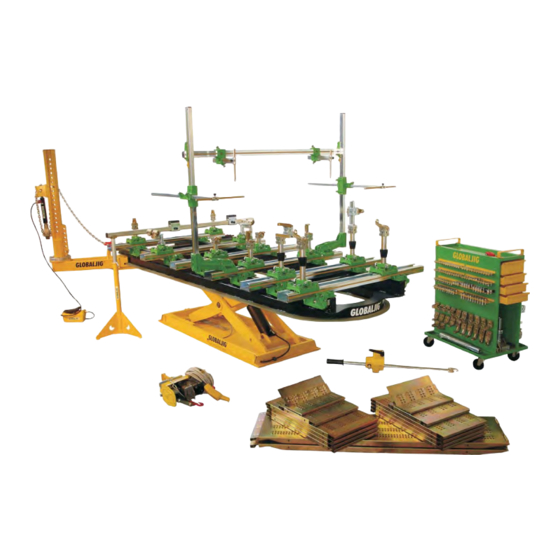
Technical description EVOLUTION is an LB designed and built to lift motor vehicles so that body repairs can be made. Its structure permits rapid lifting of the vehicle and proves ideal for use side-by- side with the more complete units: benches with jig. -
Page 17: Installation
4 INSTALLATION Transport and handling The packaging used for shipping and handling the LB is made up of: 1 wooden pallet containing the LB. Gross weight: approx. 1580 kg 1 crate containing the electric-hydraulic control unit. Gross weight: approx. 45 kg 1 crate containing the pulling arm and standard accessories. -
Page 18: Operating Environment
Operating environment The LB has been designed to work indoors. For this reason the reference environmental parameters are: temperature range between +5°C and 40°C relative humidity between 30% and 95% (without any condensation) In addition, the place where the LB is to be operated must have the following characteristics: ... -
Page 19: System Connections
System connections HYDRAULIC SYSTEM: Remove the plugs (male/female) from the hose fittings using 2 wrenches connected to one another (photos 1, 2 and 3). PNEUMATIC SYSTEM: Connect the hose with quicklock fitting (from the control unit) to pipe (on the lift). -
Page 20: Installing The Pulling Arm
Installing the pulling arm Raise the bench to about 1 mt height. Disassemble the front side of the pulling tower: Hooking attachment, spring- holder plate, springs and spacers, bearings. PICTURE 1 Insert pulling tower on the bench. PICTURE 2 PICTURE 3 PICTURE 4... - Page 21 Insert the two bearings. PICTURE 5 Position the hooking attachment, insert bolts from above toward the lower part then screw nuts and clench. PICTURE 6 PICTURE 7...
- Page 22 Blocking of the Pulling tower. Blocking is by a knob. (Picture 8) PICTURE 8 To unlock the pulling Tower pull up the knob and push toward the bench (Picture 9) PICTURE 9 Position the rod in the smallest slot, now the arm can move freely (Picture 10) PICTURE 10 To lock the arm put the Knob in the initial position.
-
Page 25: Operating Instructions
During lifting and lowering operations, the above distance guarantees greater safety should objects or the load drop from the LB ! ! WARNING ! ! GLOBALJIG declines any responsibility for anything that may result from noncompliance with the instructions in this manual. ! ! DANGER ! ! - Page 26 16° MAIN SWITCH INDICATOR LIGHT EVOLUTION BOARD FUSE 6.32X32 1A 500V FUSE 5X20 2 A BUTTON PANEL 3+G MOBILE PLUG AIR SOLENOID V. SHEATH KIT COMPLETE WITH CABLE ELECTRICAL SYSTEM COMPARTMENT MOTOR 1.85 KW 4-POLE HYDRAULIC CONTROL UNIT PRODUCT IDENTIFICATION...
-
Page 27: Operating Procedures
Operating procedures Below you will find the operating procedures that are to be performed when using the LB. a) Turning on the unit Check that the pneumatic supply is present at the control unit inlet. Check that the pneumatic supply is properly connected to the control unit and the LB. -
Page 28: Adjustments
e) Loading the vehicle on the LB Fully lower the lift and position the vehicle on it using the lift ramps. The vehicles lifted must be empty and not have anyone onboard. The LB has a tilting system that facilitates vehicle loading ! ! WARNING ! Disengage the tilting system by lowering the “tip”... -
Page 29: Safety
no unauthorized persons are in the work area. ! ! DANGER ! ! Prior authorization from GLOBALJIG must be received before applying new devices, or modifying the existing devices. Noncompliance with this point relieves GLOBALJIG of any responsibility for the modifications made. Moreover, working... -
Page 30: Residual Risks
Residual risks The user and/or operator must read this paragraph carefully to ensure that they are aware of all risks involved in the use of the LB. This information, along with a thorough reading of the entire manual, will ensure that they are fully prepared and work in the proper manner. -
Page 31: Maintenance
Technical service is guaranteed by the Manufacturer (or Area Distributor). Intervention time is limited to 48 hours (weekends and holidays not included) from the moment the call is received. Contact the GLOBALJIG Customer Services Department by telephone or fax at the following numbers: Telephone: +39 0585-8364... -
Page 32: Scheduled Maintenance
The use of anything but original, specific spare parts can alter the original configuration and lead to hazards that cannot be attributed to the LB. GLOBALJIG cannot be held responsible for any injury or damage to property or the system itself if non-original parts are used. -
Page 33: Spare Parts
When requesting spare parts, you must give GLOBALJIG the serial number of your LB, the item code and the quantity needed. This will ensure prompt identification of the part. GLOBALJIG pledges to supply said parts within 10 days of receipt of the request. -
Page 34: Instructions For Dismantling And Disposing Of The Lift Bench
9 INSTRUCTIONS FOR DISMANTLING AND DISPOSING OF THE LIFT BENCH Removing lift bench connections Before performing any operations on the LB, thoroughly disconnect all sources of power to the unit. Disconnect the system connection hoses running between the control unit and the LB. ... -
Page 35: Attachments
10 ATTACHMENTS List of attachments The EVOLUTION LB User’s Manual contains the following attachments: Lift bench dimensions Lift bench work area Electrical wiring diagram Hydraulic system diagram Pneumatic system diagram Blow-up of pulling arm ... -
Page 36: Attachment 01 - Lift Bench Dimensions
10.1 Attachment 01 - Lift bench dimensions... -
Page 37: Attachment 02 - Lift Bench Work Area
10.2 Attachment 02 - Lift bench work area... -
Page 38: Attachment 03 - Wiring Diagram
10.3 Attachment 03 - Electrical wiring diagram 400V 50Hz three-phase (N.B. check the power supply version) CONTACTOR MOTOR MOTOR HEAT SHIELD PAD TRANSFORMER EMERGENCY BUTTON UP BUTTON DOWN BUTTON LIMIT SWITCH AIR SOLENOID VALVE DOWN CONTROL OIL SOLENOID VALVE MAIN CIRCUIT BREAKER... - Page 39 10.4 Attachment 04 – Electronic data...
-
Page 40: Attachment 04 - Hydraulic System Diagram
10.5 Attachment 05 - Hydraulic system diagram... -
Page 41: Attachment 06 - Blow-Up Of Pulling Arm
10.6 Attachment 06 - Pneumatic system diagram 1 – 3-WAY PNEUMATIC SOLENOID VALVE NORMALLY CLOSED 2 – SHORT STROKE PISTON Bore dia. 3 – stroke 20 ARTEC FSR32-20... -
Page 42: Attachment 07 - Blow-Up Of Control Unit
10.7 Attachment 07 - Blow-up of control unit MANIFOLD CHOKE FILTER O-RING TANK VALVE COIL VALVE COLLAR VALVE COUPLING PUMP FILTER SUCTION TUBE CONNECTOR DISCHARGE TUBE SPECIAL NUT... -
Page 43: Attachment 08 - Figures
10.8 Attachment 08 - Figures... -
Page 44: Machine Log Book
MACHINE LOG BOOK Use the following form to make a note of the maintenance and any operations performed on the equipment. This will provide the user with the most appropriate information on the active cycle of the unit at all times. Serial number Date of initial operation Page 1/2... - Page 45 Serial number Date of initial operation Page 2/2 ....................... Signature and/or DATE Repair or programmed maintenance Spare parts stamp of the operator...
- Page 47 Capitale sociale € 100.000,00 i.v. Via Aurelia Ovest, Km. 383 - 54100 Massa (MS) - ITALY Tel.: +39 0585 8364 - Fax: +39 0585 833880 - www.globaljig.it Nessuna parte di questo documento può essere riprodotta né tradotta in altra lingua senza la preventiva autorizzazione scritta della società...
- Page 48 Società unipersonale sotto la direzione e controllo della Bellini Srl. Iscritta al Reg. Imprese di Massa Carrara al N° 01064230459 Capitale sociale € 100.000,00 i.v. Via Aurelia Ovest, Km. 383 - 54100 Massa (MS) - ITALY Tel.: +39 0585 8364 - Fax: +39 0585 833880 - www.globaljig.it...
Need help?
Do you have a question about the Evolution and is the answer not in the manual?
Questions and answers