Table of Contents
Advertisement
Quick Links
VM2 Vibration Detection
Monitor
Product Manual
(Draft 7) Jan 2020
Contents
Instruction ..................................................................................................................................................................... 2
Scope ............................................................................................................................................................................ 2
Limitations ..................................................................................................................................................................... 2
Standard System Components ..................................................................................................................................... 3
Sensor cable ................................................................................................................................................................. 3
Accessories ................................................................................................................................................................... 3
Features ........................................................................................................................................................................ 7
Installation ..................................................................................................................................................................... 8
Cable Handling ........................................................................................................................................................... 10
Tuning ......................................................................................................................................................................... 11
Operation .................................................................................................................................................................... 13
Programming Options ................................................................................................................................................. 16
Specifications .............................................................................................................................................................. 21
© JVA Technologies Pty Ltd
Page 1 of 21
Issue:20/02/2020 9:36:00 PM
Vibration monitor manual.docx
Advertisement
Table of Contents

Related Manuals for JVA VM2


Summary of Contents for JVA VM2
-
Page 1: Table Of Contents
Accessories ................................... 3 Features ..................................7 Installation ..................................8 Cable Handling ................................10 Tuning ..................................11 Operation ..................................13 Programming Options ..............................16 Specifications ................................21 © JVA Technologies Pty Ltd Page 1 of 21 Issue:20/02/2020 9:36:00 PM Vibration monitor manual.docx... -
Page 2: Instruction
Interfaces makes the system more user friendly. These options include a 4-Line Keypad, Touch Keypad, Perimeter Patrol and the Cloud Router application. There are a variety of system integration options ranging from low level IO to a HLI based on JVA’s Perimeter Patrol software. -
Page 3: Standard System Components
Draft Note: Show a basic stand alone wiring diagram. User Interfaces 4-Line Keypad The 4-Line LCD keypad can arm and disarm the VM2. It can also display some of the more important running information such as seen below. For more information see the support page. - Page 4 Cloud Router. Draft notes: At time of printing the VM2 is only recognised when emulating a Z28. See below. The voltages are fixed at 7.0kV (and are meaningless). The Alarms are live and it can be armed and disarmed. © JVA Technologies Pty Ltd...
- Page 5 Cloud Router gateway function. Draft note, the touch keypad is not compatible with the Beta test units. © JVA Technologies Pty Ltd Page 5 of 21 Issue:20/02/2020 9:36:00 PM...
- Page 6 Perimeter Patrol To connect a VM2 to Perimeter Patrol you will need a Keypad bus to USB adapter or a KPB to TCP/IP adaptor (PTE0212). For more details on Perimeter Patrol please see the Manual. Draft notes: 1) The Beta Units are not compatible.
-
Page 7: Features
Self diagnostics with on board LEDs for: Wi-Fi status PCB Error Cut or shorted cable Events All Power rails Battery Power Supply Power Relay functions © JVA Technologies Pty Ltd Page 7 of 21 Issue:20/02/2020 9:36:00 PM Vibration monitor manual.docx... -
Page 8: Installation
Installation It is recommended that all installations are performed by trained personnel. Training is available from JVA. System elements and design Installation Steps Install the WR043 sensor cable. See section x on cable handling. Draft note not yet complete Join standard RG59 cable to feed into your active zones, or to cross any areas where detection is not required. - Page 9 Jumper Configuration The VM2 is equipped with 9 jumpers. These are described in the table below. Jumper Function Purpose Inhibit Mains fail error. Fit J3 to inhibit Mains fail errors if the intention is to operate the VM2 on DC only.
-
Page 10: Cable Handling
Do not run this cable in the same conduit as electric fence lead out cable. Method for burying cable The VM2 was designed primarily as an anti-dig sensor system. For best results bury the sensor cable in coarse sand or gravel. Draft note: this section is not complete. -
Page 11: Tuning
Sample Time. This means that one long loud sound can create several Events. Note that the front end of the VM2 is done in hardware not sampling software. This means it will not miss an event even if the event is much smaller than the Sample Time. - Page 12 The VM2 has an audio output terminal on the PCB. JVA can supply a 3.5mm stereo to 3.5mm headphone cable to allow you to connect to a smart phone to record the sounds as “heard” by the VM2. You can use any MP3 sound recording App to do this.
-
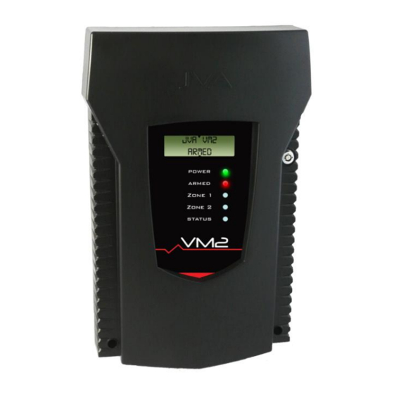
Page 13: Operation
Operation Display LEDs The LED’s on the VM2 Display PCB allow for easy diagnostics while installing the system. Power On (Green) whenever the unit has power Armed On (Red) when the unit is armed, flashing for partial armed (1 zone) - Page 14 VM2 LCD Screen The VM2 will show the status on the LCD display. When Armed While armed, the LCD display cycles the following information. Peak: means peak noise recorded in the last window of time. Avg: means the average noise level.
- Page 15 Keypad Control The VM2 contains a Virtual Keypad ™. You can use any Wi-Fi enabled device with a browser to access this. See section x. While mainly designed for configuration the Virtual Keypad ™ may also be used to arm and disarm the VM2.
-
Page 16: Programming Options
Backup Power The VM2 may be fitted with a 12V battery inside the case for backup power in case of mains fail. As the VM2 draws very little power (see section x specifications) a standard 7.5aH battery will last much longer than 8 hours. - Page 17 Filter Order. This sets the reaction time of the squelch which comes from the long term filter of the peak signal. Set to 5 (Filter time const approx 2^5 * Sample time). © JVA Technologies Pty Ltd Page 17 of 21 Issue:20/02/2020 9:36:00 PM Vibration monitor manual.docx...
- Page 18 A group of Z series devices connect on a wired Keypad Bus must have only 1 master. The other Energisers/Monitors in the group are slaves. The VM2 should be a master only if it is not in a group with Z series energisers or monitors.
- Page 19 Battery Float Set The VM2 contains an inbuilt battery charger for a standby 12V lead acid battery. If you are not using the battery ignore this setting. This setting adjusts the voltage at which a lead acid battery will be charged and held at when fully charged. Please consult your battery manufacturers specifications for the correct value.
- Page 20 Relay 6 – General Alarm Return to Factory Defaults At some point, you may want to return the VM2 to Factory Defaults. To do this remove all power from the VM2. Remove J4, reapply power and replace J4. © JVA Technologies Pty Ltd...
-
Page 21: Specifications
3 Way Form C contacts, common may be linked to 12Vdc The specifications table below outlines the power consumption of the VM2 and the acceptable voltage and current ranges for different inputs and outputs. 24Vdc Power consumption – no battery or battery fully charged 100mA 24Vdc Power consumption –...
Need help?
Do you have a question about the VM2 and is the answer not in the manual?
Questions and answers