Table of Contents
Advertisement
Quick Links
Advertisement
Table of Contents

Subscribe to Our Youtube Channel
Related Manuals for JVA VM2


Summary of Contents for JVA VM2
- Page 1 VM2 U anUal J VA T E CH N O LO G I E S www.jva-fence.com...
-
Page 2: Table Of Contents
VM2 Fence Layouts . . . . . . . . . . . . . . . . . . . - Page 3 Battery Float . . . . . . . . . . . . . . . . . . . . . . . . . . 42 JVA VM2 Manual...
- Page 4 VM2 Specifications . . . . . . . . . . . . . . . . . . .
- Page 5 JVA VM2 Manual Page 5...
-
Page 6: Quick Start Guide
Keypad or a 4-line Keypad . 2.1.1 Virtual Keypad You can connect any Wi-Fi enabled device to the VM2 (laptop or smart phone) and use a Web browser (Chrome is preferred) on this device to change the programming options. First you need to connect to the VM2 Wi-Fi module . -
Page 7: 4-Line Keypad
Press # to select this . The programming system will start to operate . Select the VM2 from the list. The programming options will be read from the VM2 and displayed in a menu system . Use the up/down arrow keys to move be- tween the options. - Page 8 50Hz. Default Off. Battery Float Battery float setting at 25C. The VM2 will charge to 1V higher on a boost cycle after a mains fail event, once per 8hrs at most . Default 13 . 7 V...
- Page 9 The function for Output 1. Default Zone 1 or Zone 2 Armed . Output 5 The function for Output 1. Default Zone 1 or Zone 2 Alarm . Output 6 The function for Output 1. Default General Alarm. JVA VM2 Manual Page 9...
-
Page 10: Jumpers
Off to return programmable options to factory defaults on power up . J5, J6 & J7 Supplies +12V to the Common terminal of Relay 3, 4, 5 . Jumpers located on the top right hand side of the board Page 10 © JVA Technologies www.jva-fence.com... -
Page 11: Vm2 Fence Layouts
2 .3 VM2 FENCE LAYOUTS JVA VM2 Manual Page 11... -
Page 12: Most Frequently Used Lcd Keypad Commands
Page 12 © JVA Technologies. -
Page 13: Introduction
The VM2 complements JVA’s range of security electric fence energisers and monitors . The VM2 is also compatible with the JVA Z-Series accessories and software solutions. The VM2 comes with an inbuilt Wi-Fi Webserver which creates a professional Virtual Keypad ™... -
Page 14: Features And Benefits
Detects hammering or crowbar bend- ing bars apart Independent settings for each Lower false alarms zone On board Wi-Fi Virtual Keypad Programming speeds up configuration Self Diagnostics On board LEDs for quick self-test . Page 14 © JVA Technologies www.jva-fence.com... -
Page 15: More Features
• Three 12V dc switch outputs (also referred to as relays) . • Three voltage free relays . • Two control Inputs configured as N/O, N/C, momentary contacts. • Input and Output functions are individually programmable. JVA VM2 Manual Page 15... -
Page 16: Description
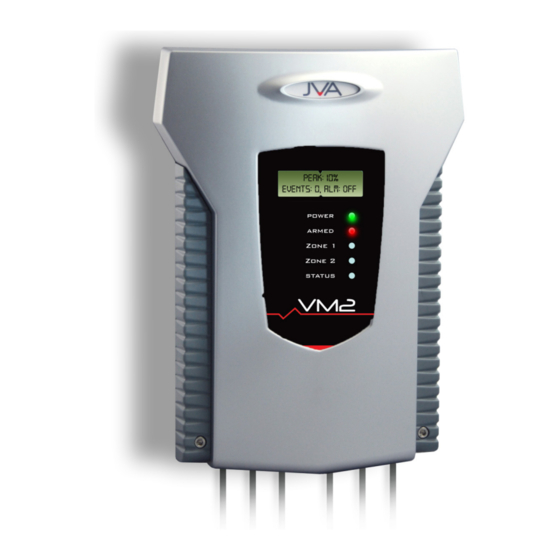
DESCRIPTION 5 .1 JVA VM2 - EXTERIOR Page 16 © JVA Technologies www.jva-fence.com... -
Page 17: Front Panel Status Lights
5 .3 FRONT PANEL LCD DISPLAY The display on the JVA VM2 shows the fence conditions for each zone. PEAK: peak noise recorded in the last window of time. AVG: the average noise level . -
Page 18: Z-Series Keypad (Optional)
5 .4 Z-SERIES KEYPAD (OPTIONAL) A Z-Series keypad allows for easy remote control of your JVA VM2 . Arming and disarming, responding to alarms or just checking the fence situation, the keypad makes this easy through a simple menu system or key sequenc- es (shortcuts) . -
Page 19: Cabling
To maintain the IPx4 rating of the enclosure and to ensure moisture does not enter the enclosure via the cable entry area a silicon sealant (neutral cure) must be used to seal all the cable passages . JVA VM2 Manual Page 19... -
Page 20: Lightning Protection
. The most likely cause of such noise is a high voltage output from an Electric Fence Energizer. In the event of erratic behaviour, check that any high voltage wiring is not arcing nearby the VM2 . The VM2 is de- signed to self-recover from interference. Powering off (both 24V dc and battery) should not be necessary. - Page 21 JVA VM2 Manual Page 21...
-
Page 22: Installation
1 . Read the entire manual first. 2 . Install the WR043 sensor cable . 3 . Join the sensor cable from the fence to the VM2 4 . Add a zone terminator (PAE346) to the end of each line . Cover with a Gel cover (MHC017) 5 . - Page 23 JVA VM2 Manual Page 23...
-
Page 24: Sensor Wiring
6 .2 SENSOR WIRING NOTE: The earth terminal must be connected to stop 50/60Hz noise from affecting the system Page 24 © JVA Technologies www.jva-fence.com... -
Page 25: 24Vdc Connection
6 .3 24VDC CONNECTION 6 .4 STROBE AND SIREN CONNECTION JVA VM2 Manual Page 25... -
Page 26: 4-Line Keypad
6 .5 4-LINE KEYPAD Page 26 © JVA Technologies www.jva-fence.com... -
Page 27: Example Group Wiring
6 .6 EXAMPLE GROUP WIRING JVA VM2 Manual Page 27... -
Page 28: Cable Handling
Do not run this cable in the same conduit as electric fence lead out cable . 7 .3 METHOD FOR BURYING CABLE The VM2 was designed primarily as an anti-dig sensor system. For best results bury the sensor cable in coarse sand or gravel . Note from research: •... -
Page 29: Websites With Useful Information
• Avoid burying next to metal • Ensure that pools of water do not sit on top of the cable 7 .4 WEBSITES WITH USEFUL INFORMATION https://www .sensoguard .com/2018/11/04/perimeter-intrusion-detec- tion-comparison-between-seismic-fiber-optic-and-leaky-coax/ https://www.deasecurity.com/media/en/pdfs/DEA-Informative-Brochure- SISMA-CP-50 .pdf 7 .5 METHOD FOR ATTACHING TO FENCE JVA VM2 Manual Page 29... -
Page 30: Tuning
This section contains information on how to adjust the adjustable param- eters to get the best balance between sensitivity and false alarms. The VM2 compares the sounds it picks up on the sensor cable to a preset limit called the Threshold . Any sound that exceeds the adjustable Thresh- old is called an Event. - Page 31 If you have an average level of over 50% something may be wrong. Check that the earth terminal on the VM2 is connected to a cabinet or site earth . You may also consider reducing the overall sensitivity of this zone fitting the Pad jumper to J11 (Zone 1) or J12 (Zone 2) .
- Page 32 Create the sounds of an intrusion on your fence or boundary and measure these . You will need someone standing by the VM2 recording the readings displayed on the VKP . The screen capture feature of most phones can be useful here .
-
Page 33: Control
A siren or strobe connected to the unit will turn on . If the VM2 is connected to an alarm system for monitoring, an alarm signal will be sent to the alarm company monitoring the alarm system . -
Page 34: Changing The User Pin
Fence, then the Siren will sound again after the “Siren Off Time“ has elapsed. If however, the fault is cleared, then the Siren will be ready to sound again for the next Alarm . Alternatively, disarming the VM2 will silence the alarm. 9 .4 CHANGING THE USER PIN •... -
Page 35: Technical Information
. Low side switched . L2+ to Strobe output for Zone 2 . Switched 12V output . A buf- fer relay should be used when connecting this output to an alarm panel . Low side switched JVA VM2 Manual Page 35... -
Page 36: Power Options
10 .2 STANDBY BATTERY Should there be a loss of mains power, the VM2 will report a mains fail fault. If the loss of power is prolonged, the battery may discharge power and become ineffective. If the battery voltage drops below the set-point, the VM2 will report a low battery fault. -
Page 37: Status Codes
If a minor error occurs, it will self-clear if the error condition is removed. A PCB fault will disarm the VM2 . The Virtual Keypad and VM2 will report more information about a PCB fault. JVA VM2 Manual... -
Page 38: Jumpers
DC only (as in solar power systems) . Factory default If the VM2 needs to be defaulted to jumper factory settings, remove all power (24Vdc and battery) and remove the Off to return pro- J4 jumper . - Page 39 A fitted Jumper is shown as closed in the diagram below. If a jumper is not to be fitted it can pe placed over a single pin, this is shown as open in the diagram below . JVA VM2 Manual Page 39...
-
Page 40: Programming Options
Group IDs . There must be a master device (Group ID 1) in the group or the system will not work . The VM2 should be set to Group ID 2 to 15 if it is wired into a group with Z series energisers or monitors . -
Page 41: Zone Events (1 And 2)
. Five events in rapid succession (within the one Window) will trigger an alarm if the Events Limit is below 5 . Reduce this to reduce false alarms. Adjust Threshold before changing this setting. The Default setting is 3 seconds. JVA VM2 Manual Page 41... -
Page 42: Sample Time
NOTE: Raising this setting will not increase the speed at which a flat bat- tery is charged. Setting it too high will damage the battery. The VM2 will run a battery “boost” cycle after an mains fail event. This will charge the battery to 1V higher (14.7V) than the normal float setting. -
Page 43: Battery Alarm
The Default setting is 5 Minutes. 11.3.12 Siren Cycles This option sets the maximum number of times the siren will sound for the Siren On Time if the alarm continues. This may be limited by local regula- JVA VM2 Manual Page 43... -
Page 44: Auto Rearm
11.3.15 Chime Mode (Option 14) This option allows the VM2 internal beeper to be used as a door chime for the gate function. When set to None, the keypad beeper is used to indicate correct keypad operation only. When set to Door Chime mode, both NOTE: “Gate Function”... -
Page 45: Input Function
The Gate Alarm will trigger after Gate is open for longer that the Gate Alarm Time . Pass Through The Input does not affect the VM2. The input state is passed through to Perimeter Patrol . Tamper The Input will generate a Tamper Alarm when triggered . -
Page 46: Output/Relay Function
Triggers on Zone 2 alarm. Latched on until the Zone is re-armed, or alarms are cleared . Strobe Zone 1 or 2 Triggers on Zone 1 alarm, Zone 2 alarm, Gate or Tam- per. Latched on until the VM2 is re-armed, or alarms are cleared . Supply Fail... - Page 47 Triggered when all zones on the Keypad Bus are armed . Group General Triggered when one zones on the Keypad Bus indi- cates a General Alarm . NOTE: The siren and strobe switched 12V outputs can be used to drive external buffer relays. JVA VM2 Manual Page 47...
-
Page 48: Vm2 Specifications
. Switched outputs Three 30V 1A “Form C” change-over contacts . Common contact can be linked to +12V Enclosure IP4x ABS plastic Size 300mm high, 190mm wide, 115mm deep Weight – packed, no battery Page 48 © JVA Technologies www.jva-fence.com... -
Page 49: Z-Series Keypads
A keypad can be used to control, program and monitor the devices on your fence . 13 .1 PTE0240 4-LINE KEYPAD JVA’s mid-range keypad features include: • Quick Arm/Disarm keys • 4-line Backlit LCD Display • Menu driven interface • Menu driven device programming •... -
Page 50: Pte0230 Touch Keypad
13 .2 PTE0230 TOUCH KEYPAD JVA’s most advanced keypad features include: • Touch screen with clean user interface designed for ease of use • Quickly arm or disarm the entire site or granularly via the Zones screen • Emails on alarm •... -
Page 51: Connecting Multiple Keypads
After connecting an LCD keypad to a group of devices, enter *68# on the keypad to ‘discover’ the connected energizers. Ensure that all Z-Series de- vices are disarmed first. JVA VM2 Manual Page 51... -
Page 52: 4-Line Keypad Commands
Page 52 © JVA Technologies. - Page 53 JVA VM2 Manual Page 53...
- Page 54 Display the Group ID of the Energizer Siren Test Battery Test Keypad Specific Function Key1 Key2 Key3 Key4 Re-Analyse the Energizer Group Keypress Beep On/Off Chimes On/Off Error Tones On/Off Keypad Alarm Tones On/Off Change Backlight Mode Display Keypad Model Page 54 © JVA Technologies www.jva-fence.com...
- Page 55 JVA VM2 Manual Page 55...
- Page 56 DEALER fEncE...
Need help?
Do you have a question about the VM2 and is the answer not in the manual?
Questions and answers