
Related Manuals for BUCKINGHAM MFG Ergovation Series


Summary of Contents for BUCKINGHAM MFG Ergovation Series
- Page 1 Designed in Conjunction with Ergovation.Doc 11-3-08 Rev. 8-26-09 P a g e PN 230216...
-
Page 2: Back View
ERGOVATION Series Sit Harness The Ergovation™ is a revolutionary ergonomically designed sit harness tested to CE standards EN 358, Standard for Work Positioning as well as EN 813 Standard for Sit Harnesses. (Note: Ergovation™ Saddle / Sit harness pictured with Omega suspension) FRONT VIEW ERGOVATION™... -
Page 3: Sizing Information
Sizing Information The Ergovation™ sit harness features a revolution in both fit and design. Due to the patented adjustable work positioning “D” rings, the load bearing webbing that hosts the “D” can be adjusted to fit a range of sizes from 24” waist all the way to a size 44” waist! What this means is that the user can adjust the “D”... - Page 4 Attachment points conforming to CE EN 358 standard EN 358 Work positioning “D” These attachment points are designed to hold the user in rings must ALWAYS position at their work station be used together (work positioning) allowing them Work Positioning to work with their hands free.
- Page 5 Gear Loops and Equipment Warning Storage Do NOT attach for positioning or suspension 22 lbs 22 lbs 10 Kg 10 Kg 22 lbs 22 lbs 22 lbs 10 Kg 10 Kg 10 Kg Gear loops must only be used to attach and support equipment.
-
Page 6: Field Of Application
Field of Application Belt for restraint and work positioning EN 358: work positioning EN 813: sit harness This product must not be loaded beyond its rated weight capacity, nor shall it be used for anything other than its designed and intended purpose. WARNING Activities involving the use of this equipment are extremely dangerous. - Page 7 ERGOVATION™ Parts Layout Do not cut this end of strap (waist strap end). See step 7 of “D” Pieces Assembly Do not cut for details. this strap details This end of strap (attachment end) may be cut to eliminate excess length.
- Page 8 Abdominal Stabilizer Assembly Instructions Step 1 Ergovation™ back pad (C) with long loop (J) and short hook (K) pieces of Abdominal Stabilizer Step 2 See next page Step3 Insert Abdominal Stabilizer (J and K) through designated slots in Back Pad (C) Ergovation.Doc 11-3-08 Rev.
- Page 9 Step 3 Insert (hook side facing up) Abdominal Stabilizer (K) snap web keepers through the designated slot in the Back Pad (C) as pictured. Repeat with loop side (J) facing down on opposite wing of Back Pad. Step 4 Pull Abdominal Stabilizer (K) through elastic band on end of Back Pad (C) as pictured.
- Page 10 Step5 Final assembly of Abdominal Stabilization System should look like this. NOTE: Loop side (J) ready to accept hook side (K) Notice loop side (J) is longer to prevent chafing of hook side (K) in the abdomen region Warning Abdominal Stabilization System is for support and comfort only, do not over tension to increase snugness of fit!! If stabilizer is too loose or tight you may need to go up or down a size in the Back pad or loop side (J short, medium or long) of the stabilizer.
- Page 11 ERGOVATION™ Assembly Instructions “D” Pieces Assembly Step 1 (Pictured left) Left Side Short “D” Piece (B) with permanently attached waist adjustment buckle. Note: Webbing of “D” Piece must be threaded through webbing loop on wing of Back Pad for proper securement - see callout left.
- Page 12 Step 3 Thread Long “D” Piece (A) through tail piece on Back Pad as pictured below. Pull through the entire length of webbing from the long “D” Piece (A) through the tail piece Step 4 Now attach the Long “D” Piece (A) to the Short “D”...
- Page 13 Step 5 Thread webbing back through top slot of the slide bar buckle to secure the Long and Short “D” Pieces together. (A and B). Step 6 Now pull the excess webbing through the slot in the tail piece of the Back Ergovation.Doc 11-3-08 Rev.
- Page 14 Step 7 Note: Consider additional length to accommodate for heavy clothing prior to cutting. If required to eliminate excess length, cut excess webbing at stitched cross section of attachment end of long “D” piece, burn end of webbing to prevent fraying and unraveling of webbing (carefully use a small flame such as that from a cigarette lighter to melt...
- Page 15 Step 9 Shift the Leg Strap Retainer Anchor into place and align snaps. Step 10 Snap the Leg Strap Retainer Anchor to the tail piece of the Back Pad for both security and ease of movement. Ergovation.Doc 11-3-08 Rev. 8-26-09 P a g e | 15 PN 230216...
- Page 16 ERGOVATION™ Assembly Instructions Waist Strap Step 1 Start with same assembly as the “D” Pieces. Thread both the Short “D” Piece (B) and the Long “D” Piece (A) together as in the “D” Piece assembly instructions on page 11. Step 2 Once the “D”...
- Page 17 Step 3 Start Finish Thread the waist strap through the larger of the two male Quick Connect Waist Buckles (E). Then through one slot of the smaller male Quick Connect Waist Buckle (F). Make a loop and pass the web back through the second slot of buckle (F) and then back through buckle (E) as shown.
- Page 18 Step 5 Insert webbing through one slot of the smaller half of the adjustment buckle (M). Then make a loop and thread the web through the second slot of the buckle to create the waist adjustment point. Step 6 Now insert webbing back through the permanently attached half of the Waist Adjustment Buckle.
- Page 19 Step 7 Repeat steps 1- 6 for the opposite side of the waist strap (female Quick Connect Buckle side (Q)). Note: Be sure that both sides of quick connect buckle line up properly before waist assembly is secured and tensioned Step 8 Once assembled place Back Pad on your waist.
- Page 20 Step 9 Once the waist strap is secured and properly tensioned it can be threaded back through the slot of the work positioning “D” ring. ® Secure the waist strap by mating the Velcro hook on the waist strap to ®...
- Page 21 ERGOVATION™ Assembly Instructions Leg Strap Assembly Inside of thigh Inside of thigh Step 1 Lay out leg pads (G) with the longer narrow side going to the inside of the thigh. Left Leg Pad Right Leg Pad Step 2 ® Place the Velcro loop side of the leg strap (D) down...
- Page 22 Step 3 Place the leg pad with the narrow side towards the inside of the thigh and the curve going up towards the buttocks. Note: Place the long strap going to the inside of the thigh and the buckle on the outside. This indicates the leg strap buckle connecting on the outside of the thigh as set up in picture #1 –...
- Page 23 Step 5 Now pull all slack through until strap fits firmly around the thigh. Note: You will not be able to just pull on strap for adjustment!! You must feed slack through buckle then take the slack out until Leg Strap is snug.
- Page 24 Step 7 Once Leg Strap is sized properly, you may cut excess webbing as shown in photo left. Burn ends to prevent fraying. (carefully use a small flame such as that from a cigarette lighter to melt the webbing fibers). WARNING You must have at least 2 stitch seams (approximately 6”) past the...
- Page 25 Step 9 Right side pad shown Now girth hitch webbing of Leg Strap Retainer around webbing of Leg Strap and Leg Pad. Note: Slide Elastic keeper on to Leg Strap Retainer before attaching to Saddle / Sit Harness. Step 10 Now layout Back Pad and Leg Straps with pads as...
- Page 26 Step 11 Before final assembly of Leg Straps to the Back Pad the Snap Webbing Keepers (P) should be added for extra security of the Leg Straps (D) and to the Leg Pads (G). Note: For best security place one Snap Webbing Keeper on each side of each Leg Pad for a total of 4.
- Page 27 Step 13 The Back Pad with Leg Strap Retainer Anchor should look like this when Leg Strap Retainers are properly inserted and oriented. Strap Retainer Step 14 Final assembly of Back Pad with Leg Straps, Leg Pads, Leg Strap Retainers, and Leg Strap Retainer Anchor.
-
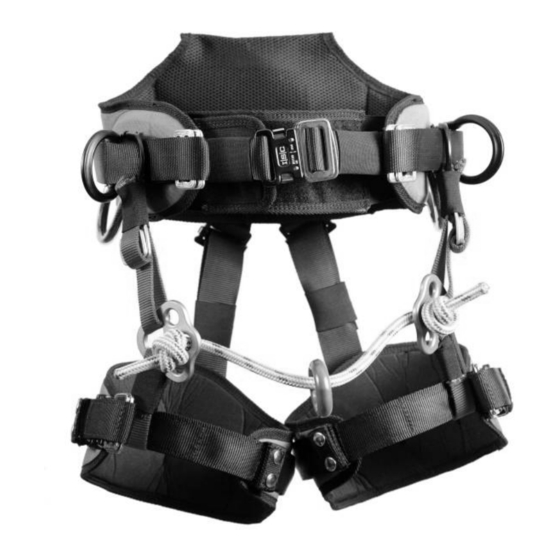
Page 28: Assembled View
ERGOVATION™ Assembly Instructions Suspension Bridge Assembly Omega Suspension pictured and featured in assembly, additional suspensions available. Assembled View Note: The Omega Suspension Bridge is supplied from the manufacturer with the minimum required tail length labels as shown below. These labels are not shown throughout this document for clarity purposes. - Page 29 Step 2 Next secure Quick Connect Buckles of Leg Strap together. WARNING Be sure to visually inspect that both sides of Quick Connect Buckle are secured, do not rely on hearing just the click of the buckle. Step 3 Once both leg straps are threaded through the loops and buckles are secured you may begin the attachment of the Suspension Bridge Assembly to the waist strap as...
- Page 30 Step 4 Buckle Insert buckle which is attached to the small D ring of the waist strap through the triangular slot in the climbing plate as pictured to the right. Climbing plate Step 5 Large buckle Once the buckle is through frame the climbing plate pull excess webbing as pictured to the...
- Page 31 Step 6 Turn the buckle at an angle and push from the underside out to fit through large buckle frame as pictured to the left. Large buckle frame Repeat steps 4 – 6 for Buckle opposite side. Step 7 Now pull on the webbing to adjust the Suspension Bridge Assembly up or down.
- Page 32 Step 8 Note: To keep yourself more upright shorten suspension adjustment straps. To lower your center of balance lengthen your suspension adjustment straps Step 9 Tuck excess webbing out of the way. Slide it underneath the elastic, to keep it from interfering with the bridge of the suspension assembly.
-
Page 33: Front View
Assembly Completed Front View Left Side View Ergovation.Doc 11-3-08 Rev. 8-26-09 P a g e | 33 PN 230216... - Page 34 ERGOVATION™ Assembly Instructions (Omega) Suspension Bridge Replacement Note: The Omega Suspension Bridge is supplied from the manufacturer with the minimum required tail Assembled View (Front) length labels shown in step 5. These labels are not shown throughout this document for clarity purposes. Climbing Plate Load Rated Ring Approved Tree...
- Page 35 Step 2 Wrap the working end twice to form a round turn around the standing part of rope. Step 3 Then insert the working end back through the two crossed round turns. Ergovation.Doc 11-3-08 Rev. 8-26-09 P a g e | 35 PN 230216...
- Page 36 Step 4 Once the termination knot is tied, dress and set the knot. Step 5 Pull the knot tight until all slack is removed from the two turns. WARNING: THREE INCHES MINIMUM OF TAIL IS REQUIRED EXITING THE TERMINATION KNOT. Ergovation.Doc 11-3-08 Rev.
- Page 37 Step 6 Now insert the terminated and tied portion of the rope into the climbing plate center hole. Insert or attach appropriate hardware onto the rope. Repeat steps 1 – 5 for opposite side. Step 7 3 in Warning Make sure Suspension Bridge has adequate tail to prevent accidental slippage. Three inches minimum of tail exiting the termination knot is required.
-
Page 38: Left Side View
Assembly Completed FRONT VIEW LEFT SIDE VIEW Warnings • Only use approved tree climbing rope for replacement bridge • The climbing rope shall have a minimum breaking strength of 5400 lbs. • The climbing rope shall be a double braid construction or kernmantle construction with load bearing core, and designated by the rope manufacture as fit for tree climbing use. - Page 39 • This product is to be used for positioning and suspension only, NOT FOR FALL ARREST UNLESS USED WITH OPTIONAL RETROFIT HARNESS. Therefore, it may be necessary to supplement arrangements for work positioning / suspension with collective means (i.e. safety nets) or personal means of protection against falls from a height (i.e.
- Page 40 Should any unusual conditions not outlined above be observed, or you have reasonable doubt about a particular condition, remove the equipment from service and notify your Supervisor, Safety Director or contact Buckingham Mfg. (1-800-937-2825) for clarification.
Need help?
Do you have a question about the Ergovation Series and is the answer not in the manual?
Questions and answers