
Summary of Contents for Azkoyen COMBO-T
- Page 1 COMBO-T Technical Information AZKOYEN Medios de Pago, S.A Tel.: +34 948 709 709 Avda. San Silvestre, s/n Fax: +34 948 709 709 www.azkoyenmediosdepago.com 31350 Peralta (Navarra) Spain...
-
Page 2: Table Of Contents
INDEX OF CONTENTS 1 INTRODUCTION 2 COMPONENTS IN THE COMBO - T 3 INSTALLATION AND START UP 3.1 DIMENSIONS AND LAYOUT 3.2 CONNECTION TO THE MASTER AND POWER SUPPLY 3.3 CONFIGURATION OF THE CCTALK ADDRESSES OF THE DEVICES 3.4 CONFIGURATION OF COIN ACCEPTANCE 3.5 CONFIGURATION OF THE COINS IN THE DISCRIMINATOR 3.6 TEST 4 DATASHEET OF COMPONENTS... - Page 3 5.5.2 Physical characteristics 5.5.3 Electrical characteristics 5.5.4 Electronic characteristics 5.6 DISCRIMINATORS 5.6.1 How the Discriminator works 5.6.2 Technical Characteristics 5.6.3 Physical characteristics 5.6.4 Electrical characteristics 5.6.5 Electronic characteristics 5.6.6 Configurations 5.6.7 Calibration of the Discriminator 5.7 ELECTRONIC INTERFACE: I/O INTERFACE BOARD 5.7.1 Functions 5.7.2 Electrical characteristics 5.7.3 Connections...
- Page 4 INDEX OF TABLES Table 1: Connections on the validator Table 2: V of power supply of the refund module Table 3: Current draw of the refund module Table 4: Types of connectors Table 5: Range of coins and exit paths Table 6: Physical characteristics of the paths Table 7: Physical characteristics of the paths Table 8: V of power supply of sorter...
- Page 5 INDEX OF FIGURES Figure 1: Principle components of the Combo – T Figure 2: Dimensions Figure 3: Connection of the interface board Figure 4: Description of components of the validator Figure 5: Connections of the validator Figure 6: Refund module Figure 7: Sorter without validator Figure 8: Diagram refund module non-autonomous Figure 9: Diagram refund module autonomous...
-
Page 6: Introduction
The information contained in this technical manual is provided as support for the use of the product and its user tools. Azkoyen Medios de Pago makes every endeavour to ensure the exactness of the information and data presented in the manual, but does not guarantee that the manual does not contain omissions or errors. - Page 7 The Combo - T device is designed to manage the processes of payment and acceptance of coins in machines or devices that use electronic payment systems. The Combo-T is a compact device, composed of several devices, for the management of coins and includes: • Coin validator with coin input chute •...
-
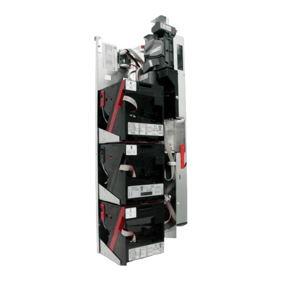
Page 8: Components In The Combo - T
COMPONENTS IN THE COMBO - T X6 D2S ccTalk Modular Validator Refund module 5-way sorter Escrow Hoppers / Discriminators • Hopper U-II • Discriminator Chassis and coin chute Electronic communication interface Figure 1: Principle components in the Combo - T 10 - 2011... -
Page 9: Installation And Start Up
INSTALLATION AND START UP 3.1 DIMENSIONS AND LAYOUT • The device should be installed on the inside of the machine taking into account the dimensions and layout that are shown below. • It is very important to ensure that both the coin exits and moving parts are free from mechanical interference, especially the coin refund motor and the opening of the validator. -
Page 10: Connection To The Master And Power Supply
Connection of the interface board Figure 3: Connection of the interface board Power supply The Combo-T device is powered from the ccTalk connection. Ensure that the power supply from the master provides the correct voltage for the operation of the equipment. •... -
Page 11: Configuration Of The Cctalk Addresses Of The Devices
3.3 CONFIGURATION OF THE CCTALK ADDRESSES OF THE DEVICES • The ccTalk device addresses of the Combo-T must be configured. • The ccTalk specification defines 1 as the bus address for the master. By default, the factory default addresses of the Combo - T devices are as follows:... -
Page 12: Datasheet Of Components
4 DATASHEET OF COMPONENTS 4.1 COIN VALIDATOR X6-D2S CCTALK VALIDATOR X6-D2S CCTALK Name: X6-D2S ccTalk Technical Voltage: 12VDC – 24VDC (±10%) Characteristics Current draw: Standby = 50 mA (±10%) Operation = 500 mA (±10%) Environment Temperature Range: +5 ºC a +55 ºC (41 ºF a 131 ºF) Specifications: Temperature Range -25ºC a +70ºC (-13 ºF a 158 ºF) -
Page 13: Refund Module
4.2 REFUND MODULE REFUND MODULES Names: /R24 Refund Motor, non-autonomous 24V /R24A Refund Motor, autonomous 24V Technical Voltage: 24VDC (±10%) Characteristics Current draw: Operation = 500 mA (±10%) Environment Temperature Range: +5 ºC a +55 ºC (41 ºF a 131 ºF) Specifications: Temperature Range -25ºC a +70ºC (-13 ºF a 158 ºF) -
Page 14: Sorter Module
4.3 SORTER MODULE SORTER MODULE Name: Sorter Module U / 5-way / ccTalk / Refund Motor / Coin entry Options: Refund motors, autonomous and non-autonomous Technical Voltage: 24VDC (±10%) Characteristics Current draw: Operation = 500 mA (±10%) Environment Temperature Range: +5 ºC a +55 ºC (41 ºF to 131 Specifications: ºF) -
Page 15: Escrow
4.4 ESCROW ESCROW Name: Escrow or V- Retainer Technical Voltage: 24VDC (±20%) Characteristics Current draw: Operation = 1.3 A (24VDC) per solenoid Environment Temperature Range: +5 ºC a +55 ºC (41 ºF a 131 ºF) Specifications: Temperature Range -25ºC a +70ºC (-13 ºF a 158 ºF) storage: Relative humidity: 95 % RH (without condensation) -
Page 16: Hoppers
4.5 HOPPERS U-II PLUS CCTALK HOPPER Name: Hopper U-II / PLUS / ccTalk / Full sensor / Empty sensor Technical Voltage: 12VDC – 24VDC (±10%) Characteristics Current draw: Start up = 3A (± 20%) Standby = 50mA (± 5%) Operation = 450 mA (±20%) Environment Temperature Range: +5 ºC a +55 ºC (41 ºF a 131 ºF) -
Page 17: Discriminators
4.6 DISCRIMINATORS DISCRIMINATOR Name: Discriminator 8 cavities / 2 coins / 24V or 24 DC / ccTalk / Full sensor / Empty sensor Technical Voltage: 24VDC (±10%) or Characteristics 12VDC (±10%) Current draw: Start up = 2.5A (± 20%) a 24VDC = 3A (±... - Page 18 Speed: Up to 5 coins/s Difference 1 mm of difference between diameter of coins for their detection diameter: Pinout connector PIN 1 = DATA in ccTalk® ccTalk: PIN 7 = PIN 10 = VDC PIN 4 = PIN 8 = GND 10 - 2011...
-
Page 19: Description Of Components
5 DESCRIPTION OF COMPONENTS 5.1 COIN VALIDATOR X6-D2S CCTALK The coin-mechanism or coin validator whose job it is to recognise and validate coins inserted by users also controls their classification. Through electromagnetic sensors and optical controlled by a digital microprocessor with technology DSP, the validator is capable of recognizing any programmed coin with a great precision, guaranteeing the functioning of free fraud and avoiding the acceptance of coins that have not been programmed. -
Page 20: How The Validator Works
• It has an effective "anti-fishing system" which has the job of foiling any attempt of fraud using the procedure of tying a string to a coin. • Modular construction. • It can control 3 and 5-way sorters. • Built with plastic material of the latest generation, wear-resistant, dissipating of static electricity, of high rigidity and dimensionally stable at high temperatures and humidity (low level of absorption) and resistant to saline mist. -
Page 21: Connections
5.1.3 Connections 1. J2 Connection - ccTalk 2. J3 Connection - modules 3. JP101 Azkoyen user Tools Figure 5: Connections of the validator Connections CONNECTOR FUNCTION PINOUT 1 – / DATA 2 – 3 – S1 SOLENOID 1 SORTER. 4 – S3 SOLENOID 3 SORTER. -
Page 22: Refund Module
5.2 REFUND MODULE It is in charge of activating the refund lever on the validator in an electro-mechanical manner, with the aim of eliminating possible mechanical jams that occur inside the validator. In addition, when a user requests the refund of credit or the cancellation of the transaction, the refund motor is activated by pressing the refund button on the interface board. -
Page 23: Refund Module. Non-Autonomous
The module itself performs the control and stopping of the motor, which should match with an opening and closing of the door of the validator. The master or primary system that controls the Combo-T should only send a pulse of activation. -
Page 24: Electrical Characteristics And Connections
5.2.3 Electrical characteristics and connections • Voltage V power supply 24VDC ± 10% Activation Table 2: V of power supply of the refund module • Current draw Current draw Activation (max.) Table 3: Current draw of the refund module Connections TYPE DESCRIPTION MODEL... -
Page 25: Sorter Module
The coins rejected by the validator are not classified but are returned to the outside of the machine by a direct reject channel. • The coins inserted in the Combo-T reach the Validator through of the coin entry chute (3). • The validator has previously received on behalf of the master ccTalk application all the commands associated with inhibition of coins and classification of them. -
Page 26: Layout Of The Classification Paths
5.3.2 Layout of the classification paths The exit paths of the sorter module (S1, S2, S3, S4 and S5) are as follows: Figure 11: Paths of classification The exit paths direct the coins to the corresponding paths C1, C2, C3, C4 and C5, to reach their final destination: filling of hoppers, intermediate storage into the escrow or cashbox. -
Page 27: Physical Characteristics
On the Electronic circuit board are the internal and external connections. The coin validator is connected to the Combo-T device with 10-way cable that comes with the sorter. Alternatively the ccTalk connection could be made with the 4-way connector available. -
Page 28: Table 9: Connections Of The Sorter
Position of the connectors on the Electronic circuit board Figure 13: Electronic circuit board Connections CONNECTOR FUNCTION CONNECTION PINOUT SOLENOIDS OF 1 – VDC J1, J2, J3 INTERNAL CLASSIFICATION 2 – SOLENOID 1 – / DATA 2 – 3 – SOLENOID 1 4 –... -
Page 29: Escrow
5.4 ESCROW This module is an optional intermediate storage of the coins inserted before making the associated transaction. It can be enabled as a classification path (C1 S1) to temporarily store coins which are not routed to hoppers or discriminators. The operation consists of the possibility of returning these coins or finally routing to the cashbox. -
Page 30: Physical Characteristics
5.4.1 Physical characteristics Range of coins Range diameter coin (mm) 16.25 to 32.5 Range thickness coins (mm) 1.2 to 3.3 Capacity (24mm dia. 2,8mm thickness) Table 10: Range of coins of the module escrow Dimensions Figure 15: Dimensions of the escrow module 10 - 2011... -
Page 31: Electrical Characteristics
5.4.2 Electrical characteristics • Voltage of power supply V power supply 12-24VDC ± 10% Activation Table 11: Voltage of power supply of sorter • Current draw Current draw Activation (max.) 1,1A Table 12: Current draw • Maximum activation time Activation times T min. -
Page 32: Hoppers
5.5 HOPPERS The Combo-T device can be equipped, as devices of payment, with both Hoppers and Discriminators. Their function is the storage of coins for the payment of refund or a credit. The main difference between a hopper and a discriminator is that the first is a single coin payout and the second has capacity to use two values of coins, simultaneously. -
Page 33: Technical Characteristics
5.5.1 Technical Characteristics • Coverage of all the range of existing coins with 3 available disks (diameter) 7, 8 and 12 cavities and two blades (thickness) • Storage of one type of coin per hopper • Up to 400 coins per hopper average for a coin of 24 mm dia. and 2.8 mm thickness •... -
Page 34: Table 17: Range Of Coins For Type Of Disk
7 and 8 cavities * For thinner coins, consult with the Dept. Short reduced 1.2 to 1.7 7 and 8 cavities CRM – after-sales Azkoyen - Ampasa Long* 1.2 to 3.3 12 cavities Table 18: Range of coins for type of blade... -
Page 35: Figure 19: View Interior Of The Extraction Device
Extraction assembly 1. Disk 2. Motor 3. Blade 4. Exit sensor 5. Propulsion trigger Figure 19: View interior of the extraction assembly Dimensions * (mm) 128,7 99,2 26,3 43,3 Figure 20: Dimensions 10 - 2010... -
Page 36: Electrical Characteristics
To select the ccTalk address of the device and to configure the operation modes, use the block of 8 dipswitches accessible from the outside. 1. Q1 – Connection ccTalk 2. Q2 – Motor 3. Q3 – Tools - Azkoyen 4. Dipswitches - configuration 5. Q4 – Sensor - full 6. Q5 – Sensor empty 7. -
Page 37: Table 21: Connections Hopper U-Ii Cctalk
8 – 0V DC 9 – 10 – VDC 1 – 2 – 0V DC (GND) CONNECTION 3 – RX AZKOYEN USER EXTERNAL 4 – TOOLS 5 – TX 6 – VDC (+5V) Table 21: Connections Hopper U-II ccTalk Circuit diagram of the driver - ccTalk... -
Page 38: Figure 23: Location Of Dipswitches For Configuration
Dipswitches for configuration The dipswitches for the selection of the ccTalk address and the configuration of the working mode are accessible from the bottom of the hopper, as shown in the figure: Figure 23: Location of dipswitches for configuration • Setting the dipswitches Selection of the address of the Hopper Not Used Selection of the address Selection of the working mode... -
Page 39: Table 22: Dip-Switch Settings
ccTalk address SW1 SW2 SW3 SW4 OFF OFF OFF OFF OFF OFF OFF OFF ON OFF OFF OFF OFF OFF OFF ON Table 23: Selection cctalk address using switches • Configuration of the working mode With switches SW7 and SW8 you establish the working mode, As shown in the table: WORKING MODE STANDARD... -
Page 40: Discriminators
5.6 DISCRIMINATORS The Combo-T device can use Discriminators as payment devices. The Discriminator is a type of hopper allowing the payment of two different types of mixed coins the same hopper. It has a device that identifies, by its diameter, the coins in the disk and allows the payment of any of the two. -
Page 41: How The Discriminator Works
5.6.1 How the Discriminator works The basis of how the Discriminator works is by measuring the diameter of the coins using three optic sensors. IMPORTANT: For the serial Discriminator to work properly, the coins that are used in the same hopper must have a difference in diameter of at least 1 millimetre. -
Page 42: Technical Characteristics
If multiple payment is used, the orders of payment must adapt to the current availability of cash. It takes into account the availability and also the percentages of the types of coins inside of the hopper. The duration of the payment will be extended proportionally to the difference of percentages of occupation of the hopper. -
Page 43: Physical Characteristics
5.6.3 Physical characteristics Range of coins Range diameter coin (mm) 18 to 30 Range thickness coins (mm) 1.2 to 3.2 Table 25: Range of coins of the Discriminator Capacity of coins in the hopper Ø 24 mm Coin Thickness cent € cent €... -
Page 44: Table 28: Range Of Coins For Type Of Blade
Types of blade Espadín corto Figure 26: Blade Blade Thickness of coins (mm) Para disk Short 1.7 to 3.2 7 and 8 cavities Short reduced 1.2 to 1.7 7 and 8 cavities Table 28: Range of coins for type of blade Dimensions (*) * Identical dimensions to the Hopper U-II * (mm) -
Page 45: Electrical Characteristics
5.6.4 Electrical characteristics • Voltage of power supply V power supply 24VDC ± 10% (*) V ATTENTION: If the Combo T device has any discriminator, the voltage of the power supply of the setup must be 24VDC. • Current draw Current draw 2,5 A ±... -
Page 46: Electronic Characteristics
5.6.5 Electronic characteristics Electronic circuit board The electronics of the Discriminator is based on a micro-controller PIC (Not flash). In contrast to the Hopper U-II, if it were necessary to update the firmware, the PIC would need to be substituted, for this reason it is removable. To select the ccTalk address of the device there are 2 dipswitches accessible from the exterior. -
Page 47: Configurations
5.6.6 Configurations Dipswitches of cctalk address The dipswitches for the selection of the cctalk address are accessible from the bottom of the hopper, as shown in the figure. • Selection of cctalk address of the device using dipswitches ccTalk address OFF OFF OFF ON Table 32: Selection of ccTalk addresses... - Page 48 For more information on the use of these and other commands, consult the document Protocolo ccTalk Discriminador_ES.pdf which is available on our website Azkoyen - Ampasa. Configuration of the payment mode The Discriminator allows the payment using two different modes: multiple payment and intelligent payment.
-
Page 49: Calibration Of The Discriminator
Payment commands standard ccTalk / Code Command Specific for discriminator [10H] About discriminator [13H] Request for status discriminator [15H] Cancellation discriminator [19H] Multiple emptying discriminator [20H] Multiple payment discriminator [23H] Last command status discriminator [35H] Intelligent payout discriminator [A3H] Test hopper standard ccTalk [A4H] Enable hopper... - Page 50 “DEVELOPMENT SOFTWARE TO CARRY OUT THE CALIBRATION PROCESS”. The recalibration may be done by the machine, if you have implemented this provision in your software or with the ccTalk Manager Tool of Azkoyen, follow the steps listed in the chapter: “Execution of processes Discriminator Calibrate”, page 24.
-
Page 51: Electronic Interface: I/O Interface Board
5.7 ELECTRONIC INTERFACE: I/O INTERFACE BOARD The Combo - T connects to the master of the system through this interface board, using a standard of 2 x 5 - way ccTalk connection. In addition to the ccTalk connection, it has a microcontroller for the control of the ccTalk devices working in parallel, such the refund motor and the escrow and the reading of analogue / digital inputs to receive information on the status of the devices. -
Page 52: Connections
5.7.3 Connections 1. JP1 principle connection - ccTalk 2. JP5 Azkoyen tools 3. JP4 escrow and inputs a / d 4. JP3 refund button 5. JP2 refund motor Figure 30: Description of connections Connections CONNECTOR FUNCTION PINOUT 1 – / DATA 2 –... -
Page 53: Description Of The Cctalk Commands
5.7.4 Description of the ccTalk commands CcTalk addresses of the interface board The interface board, by default, has the cctalk address 80 (decimal) assigned. It is possible to change this address for any of the 85-89 range, using the command ccTalk [251] Address change. - Page 54 Description of commands All the commands except 70, 71, 72 and 96 are specific ccTalk protocol commands (v. 4.5). For more information on this protocol, see: www.cctalk.org Header 96: Request module information Transmitted data: <none> Received data: [type of I/O][details][version firmware][00][00] Use this command to inform on the type of device and its firmware version.
- Page 55 Header 71: Control motor refund Transmitted data: <none> Received data: ACK This command is used to activate the refund motor. This will stop if its input is set to 0 (stop motor = ON) Header 70: Control V retainer Transmitted data: [charge/refund] Received data: ACK This command is used to activate the V retainer.
-
Page 56: User Tools
PC or through of the portable tool TL20. There is a specific manual, both for the TL20 and the HEUS, available on the Azkoyen website; you should consult them for the detailed instructions for managing and operating these devices. -
Page 57: Portable Tool Tl20
The application is available on the technical website of Azkoyen (http://sat.azkoyen.com). Figure 33: Screen shot of the application ccTalk Manager The ccTalk Manager facilitates the integration of the Combo - T or any other ccTalk device, using simulation of the communication. -
Page 58: Cctalk Interfaces
For the connection of ccTalk devices to a PC you need an electronic interface that suits the voltage to be used in this serial communication. There are two available interfaces, one with a USB connection and the other with a RS-232 connection, to be connected to a COM. 6.2.2 ccTalk interfaces 6.2.2.1 Interface USB –... -
Page 59: Figure 35: Interface Rs232 - Cctalk
Figure 35: Interface RS232 - ccTalk It is necessary to power the device with a power supply of 12 or 24VDC depending on the voltage that is needed by the devices on the bus. 10 - 2010... -
Page 60: Norms
7 NORMS. CE CERTIFICATION Like Azkoyen products, Combo-T meets regulations electromagnetic compatibility and others related with security compliance of its components: • UNE-EN 61000-6-3:2007, Electromagnetic Compatibility (EMC). Part 6-3: Generic Standards. Emission standard for residential, commercial and light- industrial environments. -
Page 61: Rohs Certificate
RoHs CERTIFICATE 10 - 2010... -
Page 62: Reach Directive Certificate
REACH DIRECTIVE CERTIFICATE 10 - 2010...
Need help?
Do you have a question about the COMBO-T and is the answer not in the manual?
Questions and answers